2 Instrument Configuration
Copyright © WOODLEY EQUIPMENT COMPANY LTD.
53
1 - 12V and 24V power input interface
2 - 24V testing point
3 - 12V testing point
All power inputs on the main control panel derive from the power input of the device. If either of the
power inputs on the main control panel receives a surge from a grounded or any other input power
source, the device’s power supply will activate its automatic protection mechanism and produce a
buzzing sound.
For the normal status of power indicator lights shown in the figures above, please refer to the
descriptions of the power supply and indicator lights of the main control panel in
Composition of the Main Control Panel
. If the power indicator light is in a status different from
normal, this means that the power supply is not working properly.
U11 deserves further description as follows. U11 is the ARM power management chip in the digital
section of the main control panel. The working status of this chip determines the working status of
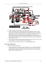
the main control panel. As shown in Figure 2-42, D14 turned on indicates the proper working of U11.
Figure 2-42 ARM power management chip in the main control panel
1 - Power management chip U11
2 - U11 working indicator
Functional Problems with the Main Control Panel and their Indicators
Functional problems with the main control panel are typically related to one of two causes. One
cause may be that the counting function of the main control panel cannot be realised. For example,
the digital part’s operating system on the main control panel is not operational, the FPGA program
does not load, or there is abnormal counting. The other cause refers to control failure of the motor,
valve-pump, temperature control, etc.
Содержание InSight V5
Страница 1: ...DMR MB 007 1 5...
Страница 126: ...7 Maintenance Inventory Copyright WOODLEY EQUIPMENT COMPANY LTD 120...
Страница 127: ...7 Maintenance Inventory Copyright WOODLEY EQUIPMENT COMPANY LTD 121...


