Watlow PM LEGACY™ Limit Controller
•
7
•
Chapter 1 Overvie
w
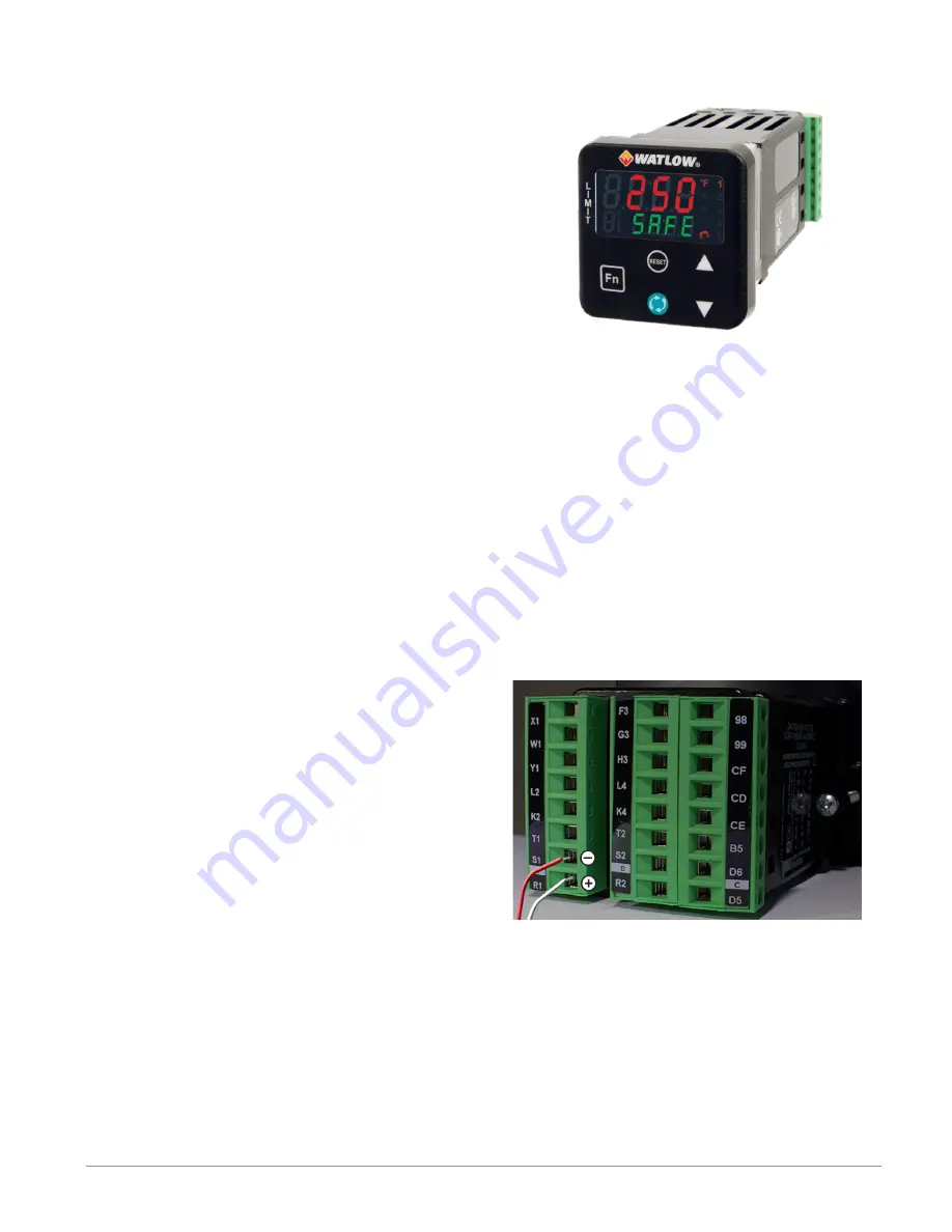
Figure 2: Input Terminal Connections
Shown Here
Overview
A Conceptual View of the PM
The flexibility of the PM software and hardware
allows for a large range of configurations. Ac-
quiring a better understanding of the controller’s
overall functionality and capabilities while at the
same time planning out how the controller can be
used will deliver maximum effectiveness in your
application.
It is useful to think of the controller in terms of
functions; there are internal and external func-
tions. An input and an output would be considered
external functions where the limit, PID or alarm
function would be an internal function. Information
flows from an input function to an internal func-
tion to an output function when the controller is
properly configured. A single PM controller can
carry out several functions at the same time, for
instance (but not limited to), checking for a limit
condition, monitoring for several different alarm
situations, etc... To ensure that the application
requirements are being met, it is important to first
give thought to each external process and then
configuring the controller’s internal functions to
properly accommodate the application require-
ments.
Inputs
The inputs terminal connections are located on the
back side of the controller. See Figure 2. The con-
troller, properly wired and configured will provide
the information that any given programmed proce-
dure can act upon. In a simple form, this informa-
tion may come from an operator pushing a button
or from a sensor monitoring the temperature of a
part being heated or cooled.
Each analog input typically uses a thermocouple
or RTD to read the process temperature. It can
also read volts, current or resistance, allowing it to
use various devices to read a wide array of val-
ues. The settings in the Analog Input Menu (Setup
Page) for each analog input must be configured to
match the device connected to that input.
Figure 1: PM6 Controller Shown Here
A PM with digital input/output (DIO) hardware in-
cludes two sets of terminals where each of which
can be used as either an input or an output. Each
pair of terminals must be configured to function
as either an input or output with the direction pa-
rameter in the Digital Input/Output Menu (Setup
Page). Each digital input reads whether a device
is active or inactive.
The Reset Key on the front panel of the PM also
operates as a digital input by toggling the func-
tion assigned to it in the Digital Input Function
parameter in the Reset Key Menu (Set-up Page).
Содержание PM LEGACY PM3
Страница 119: ...Watlow PM LEGACY Limit Controller 119 Appendix...


