


Velocity Operation Manual
www.velocitydetection.com
60
‘Disabled’ selection circle, then press
or
to cycle
through more outputs, or the exit icon
. The panel
will ask if you want to save the changes.
Press tick
to save the changes, or press
to
discard.
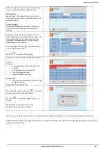
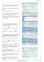
NCA/NCB Disablement
The module settings screen will be displayed.
In this example, the output address is shown as:
(2.1)
.
The first number represents the TRM port (The RJ45 port
on the TRM PCB that the module is plugged into). The
second number represents the output on the module
itself.
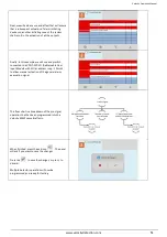
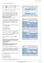
E.g. a NCB that is plugged into TRM port 2 would have
the following addresses:
(2.1) = TRM Port 2, Output 1
(2.2) = TRM Port 2, Output 2
To disable an input, change the mode by pressing on the
‘Disabled’ selection circle, then press
or
to cycle
through more inputs, or the exit icon
. The panel will
ask if you want to save the changes.
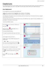
Press tick
to save the changes, or press
to
discard.
When a module has a disablement, the LCD display
changes from SYSTEM NORMAL to Disablement. The
screen shows:-
The number of disabled alarm groups.
The number of disabled local I/O.
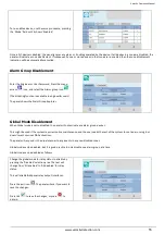
The General Disablement LED will be lit with any module
disablement.
The General Disablement and NAC disablement LED will
be lit if a NCA or NCB port is disabled.
Details of the disabled module inputs/outputs can be
viewed by pressing the disabled local I/O icon
. If any
zones have all of their outputs disabled, it will be
indicated by the disabled zone outputs icon
.