Velocity Operation Manual
www.velocitydetection.com
58
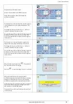
For further options, press the ‘Out’ field again. The status
will change from ‘Relay disabled’ to ‘All disabled’.
This would disable all sounder and relay outputs in that
alarm group (zone).
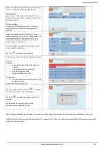
When Alarm group mode has been disabled, the LCD
display changes from SYSTEM NORMAL to Disablement.
The screen shows:-
The number of disabled alarm groups.
The number of disabled SLC devices.
The number of disabled module outputs.
The General Disablement and NAC disablement LED will
be lit if Sounder disabled or All disabled was selected.
Only the General Disablement LED will be lit if just Relay
disabled was selected.
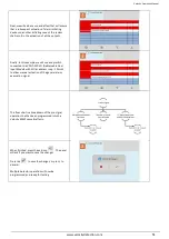
Details of the disabled alarm group outputs can be
viewed by pressing the disabled loop devices icon
or
the disabled local I/O icon
. If any zones have all of
their outputs disabled, it will be indicated by the disabled
zone outputs icon
.
To re-enable a zone, use the same procedure, pressing the
“Out” field until it shows ‘All Enabled’.
It cycles through:-
•
All enabled
•
Sounder disabled
•
Relay Disabled
•
All Disabled
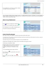
Press the exit icon
. The panel will ask if you want to
save the changes.
Press tick
to save the changes, or press
to
discard.
Local I/O (Module) Disablement
When a local I/O is disabled, the panel will not react to any alarm or trouble signal from that local I/O (module).
This might be used if the system requires routine maintenance, and the user needs the rest of the system to continue running, but
doesn’t want spurious input/output activations.
The panel will respond in the usual manner to any events in any non-disabled parts of the system.
Any number of local I/O’s can be disabled, but it is good practice to only disable one at a time.


