Velocity Operation Manual
www.velocitydetection.com
23
Setting NCA & NCB Module Options
The below is an example on how to change the VL/NCB options. The procedure to change the settings for the VL/NCA is the same.
Note that the cause & effect for the Velocity MMP panel has 3 tone options for the NACs: ANSI -3 tone, March tone and continuous.
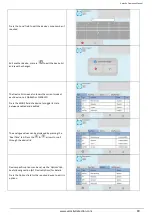
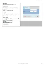
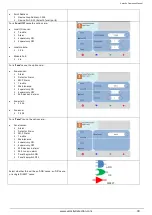
From the ENGINEER MENU, press the Local I/O Icon.
The panel will show the module selection screen.
Select the required port number. The port number is
shown in the brackets on the left. When you select a
module it will become highlighted. The up and down
arrows can be used to cycle through pages. Press the
green tick to confirm the selection.
Panel Designations:
VL/NCA (NAC – 1 x Class A) = Sounder Class A
VL/NCB (NAC – 2 x Class B) = Sounder Class B
The port number will be labelled on the TRM PCB
inside the panel and are also shown in the Velocity
Installation manual (Doc: GLT-261-7-1).
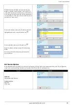
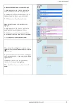
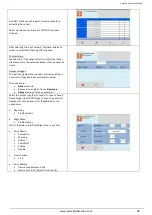
The module settings screen will be displayed.
In this example, the output address is shown as: (3.1).
The first number represents the TRM port (The RJ45
port on the TRM PCB that the module is plugged into).
The second number represents the output on the
module itself.
E.g. a NCB that is plugged into TRM port 3 would have
the following addresses:
(3.1) = TRM Port 3, Output 1
(3.2) = TRM Port 3, Output 2
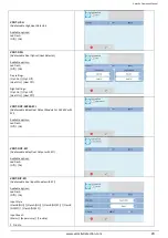
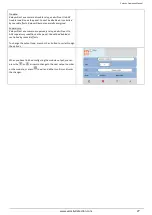
To change the text label of a module output, press on
the text label field. This will display the panel
keyboard. Enter the required text name, and then
press the green tick to confirm.
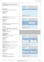
Each output can be assigned to a zone. To change the
zone, press either the + or – button to increase or
decrease the zone number.
You can also type in the number via the panel
numerical keyboard, to do this press on the zone
number field. Type in the required zone number and
press the green tick to confirm.


