Diagnostics and repair
LFXG-H Installation and Operation Guide
85
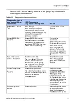
Jumpers
Jumpers JP1 and JP2 on the power supply board set the current loop
source or sink mode.
The level gauge does not use jumpers J1 – J4 on the CPU board.
Table 5.5
CPU test point labels
Label
Description
Count
Raw input signal coming from the preamplifier.
GND
Logic ground
U5 pin 8
+5 V power supply test points. Referenced to logic ground.
Note:
Do not change the jumpers from the current setting without
calling VEGA Field Service.
Table 5.6
Jumper settings
Mode
Gauge current loop
Jumper setting
Source mode
Self-powered
JP1 1-2, JP2 2-3
Sink mode
DCS-powered
JP1 2-3, JP2 1-2
Содержание FiberFlex LFXG-H
Страница 2: ......
Страница 4: ...ii LFXG H Installation and Operation Guide NOTES...
Страница 6: ...iv LFXG H Installation and Operation Guide...
Страница 14: ...Preface xii LFXG H Installation and Operation Guide...
Страница 34: ...Installation 32 LFXG H Installation and Operation Guide FiberFlex mounting...
Страница 91: ...Diagnostics and repair LFXG H Installation and Operation Guide 89 Source Functions...
Страница 100: ...98 LSGH Installation and Operation Guide NOTES...
Страница 101: ......


