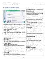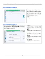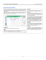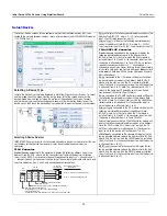
Console Touch Screen Overview
TLS4 Comm Ports - Menu>Setup>Communication
4
Entering Changes On A Touch Screen
The screen example below describes entering data into the screen’s field windows.
Console Comm Ports
When setting up comm ports, you should verify the connections to the console’s comm ports prior to entering their setup
parameters.
TLS4 Comm Ports -
Menu>Setup>Communication
Your console’s Comm Port configuration will depend on features ordered. Note: Ethernet ports 2 and 3 are programmed as
the same ethernet device.
Figure 1. TLS4 Comm Ports
After maki
n
g a
n
y cha
n
ge to a
s
cree
n
e
n
try, to
u
ch the key to acce
p
t the
cha
n
ge(
s
) or to
u
ch the key to
ca
n
cel the cha
n
ge(
s
).
System Status
07/20/2013 09:01 AM
Printers
0 Warning(s)
0 Alarms(s)
Print (0)
Home
Favorites
Menu
Actions
Setup
Configured
Driver Selection
Printer
Is Default
Label
URI
1
APS_CP324HRS_640_USB_1
TLSIntegralPrinter
dev/bus/usb?type=usb+vid=6868+pld=4
Yes
No
Enabled
Disabled
Automatic
Manual
Setup
1
Printer
4
e
a
n
ca
n
4
Afte
e
n
t
cha
A graye
d
-i
n
fiel
d
ca
nn
ot be cha
n
ge
d
.
I
n
thi
s
e
x
am
p
le, if there two or more
p
ri
n
ter
s
, the fiel
d
wo
u
l
d
be white a
nd
to
u
chi
n
g the
d
ow
n
arrow wo
u
l
d
d
i
sp
lay
the a
dd
itio
n
al
p
ri
n
ter
s
.
To
u
chi
n
g i
n
a white fiel
d
d
i
sp
lay
s
a
p
o
p
-
up
keyboar
d
/key
p
a
d
to e
n
ter
or mo
d
ify a
n
e
n
try.
S
electe
d
d
evice. To
u
ch to
s
elect
a
dd
itio
n
al
d
evice
s
to be
p
rogramme
d
,
i
n
thi
s
ca
s
e a
dd
itio
n
al
p
ri
n
ter
s
.
If
p
age
s
croll i
s
vi
s
ible, to
u
ch the
up
/
d
ow
n
arrow
s
or
s
li
d
e bar with fi
n
ger to
s
croll
up
or
d
ow
n
to view a
dd
itio
n
al e
n
try fiel
ds
.
A
n
a
s
teri
s
k (*)
n
e
x
t to a fiel
d
i
nd
icate
s
yo
u
cha
n
ge
d
a
n
e
n
try for that fiel
d
before yo
u
have acce
p
te
d
or
s
ave
d
the cha
n
ge i
n
a
d
ialog wi
nd
ow.
White (em
p
ty) ra
d
io b
u
tto
n
i
nd
icate
s
item i
s
n
ot
s
electe
d
.
To
u
ch ra
d
io b
u
tto
n
to
s
elect Di
s
able
d
a
nd
d
e
s
elect E
n
able
d
.
To
u
ch
d
ow
n
arrow i
n
a me
nu
brea
d
cr
u
mb to view all a
dd
itio
n
al
s
et
up
s
cree
ns
,
s
elect a
n
y i
n
li
s
t to j
u
m
p
to that
s
cree
n
y,
g
e
d
itio
n
al
p
ri
n
ter
s
.
s
croll
maki
n
g
to
u
ch
ge(
s
) or
el the c
i
g
t
r
h
ow
e bar with fi
n
ger to
s
croll
dd
iti
l
t
fi l
d
cree
n
e
p
t the
to
e
up
/
d
o
b
ith fi
t
ll
s
e
y
s
vi
s
ible, to
u
ch the
g a
n
y
y
y
y
y
y
y
cha
n
ge to a
s
the key to acc
to
u
ch the key
ha
n
ge(
s
).
*
USB port (1) upper
USB port (2) lower
SWITCH ETH 2 & 3 - shown
in Setup menu as
Ethernet Port 2 (Optional)
Factory Installed,
Optional Module
Area
VR Bus port
Ethernet port (1)
RS-232 or RS-485 DB9 ports
EXPANSION
SERIAL 1
SERIAL 2
ETH 2
ETH 3
USB 1
USB 2
ETH 1


