Initial Setup Of The Console Using Workflow Wizard
Setup>Devices
19
Setup>Devices
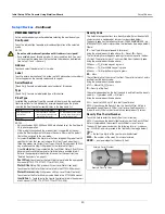
The Setup>Device screens let you configure each of the
m
onitored devices that is con-
nected to the console (probes, sensors, relays, external inputs) and (LVDIM/MDIM
m
odules
- TLS-450PLUS only).
Relay will display the following possible address codes in the
Address Field: B1:S1:X , where X = 14 (relay connector
input 1) or 15 (relay connector input 2).
External Input will display the following possible address
codes in the Address Field: B1:S1:X , where X = 12 (Ext.
Input connector input 1) or 13 (Ext. Input connector input 2).
TLS-450PLUS Consoles
Probes/Sensors connected to the console will display the
following possible address ports in the Address Field:
B1:Sx:X, where Sx is the slot in which the USM
m
odule is
installed (fro
m
1 to 4) and X is the connector input to which
the device is attached (fro
m
1 to 16). NOTE: 3-wire sensors
require three connector inputs (2 ‘+’ channels and 1’ – ‘
channel) so each 3-wire sensor takes up two of the available
intrinsically safe ports and has two addresses (
Address
field
and
Address 2
field (see 3-Wire Sensor Addresses Exa
m
ple
illustration above).
Relays connected to the I/O
m
odule will display the follow-
ing possible address codes in the Address Field: B1:Sx:X,
where Sx is the slot in which the I/O
m
odule is installed
(fro
m
1 to 4) and X is the connector input to which the device
is attached (fro
m
5 to 9). Note: The relay address B1:S7:1
refers to the single input Power Bay relay which, if used,
would connect to the site’s Overfill Alar
m
.
Relays connected to a 10 AMP Controller
m
odule will display
the following possible address codes in the Address Field:
B1:S4x:X, where S4 is the only slot in which the 10 AMP Con-
troller
m
odule is installed and X is the connector input to
which the device is attached (fro
m
1 to 6).
External Inputs connected to the I/O
m
odule will display the
following possible address codes in the Address Field:
B1:Sx:X, where Sx is the slot in which the I/O
m
odule is
installed (fro
m
1 to 4) and X is the connector input to which
the device is attached (fro
m
1 to 4 and 10 to 14).
External inputs connected to a 10 AMP Controller
m
odule will
display the following possible address codes in the Address
Field: B1:S4x:X, where S4 is the only slot in which the 10
AMP Controller
m
odule is installed and X is the connector
input to which the device is attached (fro
m
7 to 12).
LVDIM inputs connected to the console will display the fol-
lowing possible address codes in the Address Field: B1:Sx:X,
where Sx is the slot in which the LVDIM
m
odule is installed
(fro
m
1 to 4) and X is the connector input to which the device
is attached (fro
m
1 to 12).
MDIM inputs connected to the console will display the fol-
lowing possible address codes in the Address Field: B1:Sx:X,
where Sx is the slot in which the MDIM
m
odule is installed
(fro
m
1 to 4) and X is the connector input to which the device
is attached (fro
m
1 to 12).
S
electing A Device Type
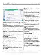
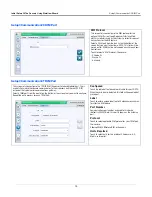
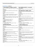
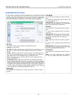
Initially the first device type to be displayed in Workflow Wizard setup is Probe 1. To select
another probe, touch the probe 1 button on the lower left of the screen and select the
desired probe fro
m
the icon list along the botto
m
of the probe device screen. To select
another device type, use the touch sequence shown in the illustration below to view the
device
m
atrix, then touch the desired device type button to open that device’s setup screen.
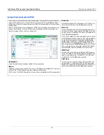
S
electing A Device Address
IMPORTANT! You
m
ust know to which console connector a device is wired to select the cor-
rect address for that device. So
m
e general rules discussed below concern device
addresses.
TLS4 Consoles
Probes/Sensors connected to the console will display the following address code in the
Address Field: B1:S2:X , where x is the connector input to which the device is attached
(fro
m
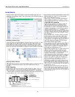
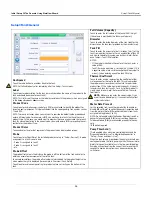
1 to 16). NOTE: 3-wire sensors require three connector inputs (2 ‘+’ channels and 1 ’
– ‘ channel) so each 3-wire sensor takes up two of the available intrinsically safe ports and
uses two addresses (see 2- and 3-wire connection exa
m
ples below):
Actions
1
Probe
Water
Next
Actions
1
Probe
Probe
1
2
3
4
Serial Number
Type
Float Type [inch
Previous
Next
Actions
1
Probe
Probe
1
2
3
4
Address
Label
Serial Number
Type
Float Type [inch
External Input
Liquid Sensor
Type A Sensor
Type B Sensor
Line Pressure Sensor
LVDIM
ATM Pressure Sensor
Vapor Pressure Sensor
Ground Water Sensor
Groundwater Sensor
Example Port Address
Selections
Console
Connections
3-Wire
Sensors
All
2-Wire
Sensors
B1:S1:1 Address Field Selection
B1:S1:2 Address 2 Field Selection
Vapor Sensor
GRN
WHT
RED
GRN
WHT
BLK
RED
BLK
WHT
BLK
WHT*
4Site Pan/Sump (Type B) - Standard and Optical
1
2
Not
us
e
d
with
3
-wire
s
e
ns
or
*Red wire instead of White for:
• Interstitial Sensor - Steel Tanks (794380-4X0)
• CSTP Liquid Switch
• Position Sensitive Interstitial Sensor - Steel Tanks (794380-333)


