


Initial Setup Of The Console Using Workflow Wizard
Setup>Devices
22
Setup>Devices
- Continued
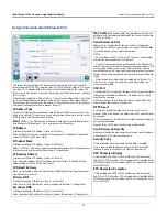
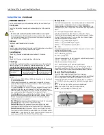
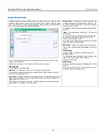
TYPE B SENSOR (3-WIRE CL) SETUP
Set up each Type B sensor being
m
onitored before selecting the next device
type.
Configured
Touch the radio button to enable or disable configuration of the selected
Type B sensor.
Address
Touch and select address 1 of the 3-wire Type B sensor.
Label
Touch to enter a description of this Type B sensor (up to 20 alphanu
m
eric
characters) that will appear on the console screens and in reports.
Address 2
Touch and select the next sequential address for the third wire of the Type B
sensor (e.g., if the
Address
field above is B1:S2:2, then this address should
be B1:S2:3).
Model
Touch and select the
m
odel of this Type B sensor:
•
Ultra/Z-1
- 4Site Pan/Su
m
p - Standard.
•
Ultra/Z-1 HV
- 4Site Pan/Su
m
p - High Vapor.
Category
Touch to select Type B sensor category:
• Annular Space •Dispenser Pan • Monitoring Well • STP Pu
m
p
• Contain
m
ent Pu
m
p •Other
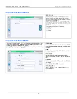
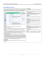
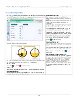
MAG SENSOR SETUP
Set up each Mag sensor being
m
onitored before selecting the next device
type.
Configured
Touch the radio button to enable or disable configuration of the selected Mag
sensor.
Address
Touch and select the address of this Mag sensor.
Label
Touch to enter a description of this Mag sensor (up to 20 alphanu
m
eric char-
acters) that will appear on the console screens and in reports.
Serial Number
[Read Only] Console auto-detected serial nu
m
ber of this Mag sensor.
Alarm Delay
Touch to enter the ti
m
e in hours following the triggering of un-cleared warn-
ings before they are upgraded to alar
m
s.
Fuel Alarm
Touch to enter the height at which this Mag sensor will activate the fuel
alar
m
.
Fuel Warning
Touch to enter the height at which this Mag sensor will activate the fuel
warning.
Water Alarm
Touch to enter the height at which this Mag sensor will activate the water
alar
m
.
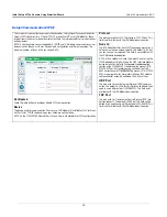
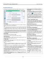
MAG SENSOR SETUP - Concluded
Water Warning
Touch to enter the height at which this Mag sensor will activate the water
warning.
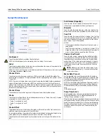
GROUNDWATER SENSOR SETUP
Set up each groundwater sensor being
m
onitored before selecting the next
device type.
Configured
Touch the radio button to enable or disable configuration of the selected
groundwater sensor.
Address
Touch and select address 1 of the 3-wire groundwater sensor.
Label
Touch to enter a description of this groundwater sensor (up to 20 alphanu-
m
eric characters) that will appear on the console screens and in reports.
Address 2
Touch and select the next sequential address for the third wire of the
groundwater sensor (e.g., if the
Address
field above is B1:S2:4, then this
address should be B1:S2:5).
Category
Touch to select this groundwater sensor category:
• Annular Space • Dispenser Pan • Monitoring Well • STP Pu
m
p
• Contain
m
ent Pu
m
p •Other
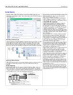
VAPOR SENSOR SETUP
Set up each vapor sensor being
m
onitored before selecting the next device
type.
Configured
Touch the radio button to enable or disable configuration of the selected
groundwater sensor.
Address
Touch and select address 1 of the 3-wire vapor sensor.
Label
Touch to enter a description of this vapor sensor (up to 20 alphanu
m
eric
characters) that will appear on the console screens and in reports.
Address 2
Touch and select the next sequential address for the third wire of the
vapor sensor (e.g., if the
Address
field above is B1:S2:6, then this
address should be B1:S2:7).
Threshold
Touch to enter the vapor level which identifies a leak or serious spillover and
that triggers the vapor alar
m
. Thresholds are in oh
m
s and
m
ust be calcu-
lated for each vapor sensor (see Vapor Sensor Threshold topic for deter
m
in-
ing value).
Category
Touch to select this vapor sensor category:
• Annular Space • Dispenser Pan • Monitoring Well • STP Pu
m
p
• Contain
m
ent Pu
m
p • Other