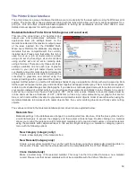
Image Enhancements
This section contains settings for enhancing and improving raster imaging.
Texturize
Texturize is a special feature which adds random variation to the laser power level assigned to each
color. This is useful for creating a textured effect on engraved surfaces to mask grain lines and motion
artifacts. One useful application of this feature is when engraving away large areas of acrylic, but for
most applications this feature is not necessary.
Tuning
Tuning shifts the left to right and right to left raster strokes the motion system makes when Rastering
an image so that they line up vertically with respect to each other. This is necessary to compensate
for laser response and mechanical lag when rastering at high speeds. A misadjusted TUNING value
will cause the image to appear double- imaged or bolder than normal and edges may not be sharp
and defined. The optimum tuning value will vary by material and speed of processing. TUNING will be
different if you have Image Enhancements enabled vs. disabled. A typical TUNING value can be from
-8 up to 0 depending on speed of processing. If you use the materials database, nominal tuning
values are already set for you. You can look up the tuning value for a particular material in the
database by selecting that material in the materials database tab and selecting edit. Keep in mind that
the tuning value is optimized for the particular raster speed and power level stored in the database. If
you need to change the speed or power significantly for your application, you may need to determine
a new value by testing. Also remember that the tuning value is affected by raster enhancement
settings so if the material database record has image enhancements turned on, you should use those
values along with the tuning value.
Procedure For Setting The Tuning Value
An easy way to set the tuning value on a given material at a desired processing speed is to create a
graphic consisting of about 20 thin vertical lines about 1” (25.4 mm) tall and .010” (.254 mm) apart in
the center of the engraving field. The lines should have a line thickness of .001” (.0254 mm) if
possible in the graphic application being used, otherwise use the thinnest the application allows. Then
print the graphic to the laser system as a raster image by forcing the color the lines are drawn in to be
in rast mode in the color table and the image density to 1 (draft mode). Make sure you set your speed
of processing equal to the speed you plan to run your application at and the laser power set high
enough to mark the material. This will result in vertical lines that look dotted. You can then look at the
dots and if they are not lined up vertically, adjust the tuning value by 1-2 ticks and try again. Repeat
until the dots in the dotted lines are lined up vertically.
Note:
If you need to use image enhancements for you application, you should use the image
enhancement tuning procedure in place of this procedure.
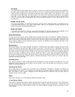
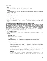
Image Enhancement Dropdown Menu
Various Image Enhancement modes improve marking and engraving quality at high speed by
compensating for laser response in order to make edges crisp and defined and to keep thin
elements of a graphic being printed, such as certain fonts (especially at small font sizes) and thin
vertical lines, from fading out. Four Modes are available: Disabled, Manual, Automatic with
margins, Automatic without margins.
Note:
The Image Enhancement feature is not available in 3D or rubberstamp printing modes.
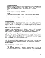
Automatic Enhancements With Margins (Drop Down Menu)
Calculates optimal enhancements but with margins on either side of the printing for best edge
quality. With margins added the motion system over-strokes (travels beyond the edge of the print
data) so that the motion system does not try to laser mark or engrave while it is accelerating or
64
Содержание PLS4.75
Страница 1: ...PLS User Guide PLS4 75 PLS6 75 PLS6 150D PLS6MW www ulsinc com Revision August 2012...
Страница 5: ...Chapter 1 Specifications 5...
Страница 8: ...Chapter 2 Safety 8...
Страница 14: ...Tamper Proof Labels Safety Labels...
Страница 15: ...ULS Fiber Laser Cartridge Labels 15...
Страница 16: ......
Страница 17: ...PLS4 Back View 17...
Страница 18: ...PLS6 Front View 18...
Страница 19: ......
Страница 22: ...Chapter 3 Installation 22...
Страница 40: ......
Страница 48: ...Chapter 4 Operation 48...
Страница 83: ...Chapter 5 Accessories 83...
Страница 99: ...Example Connection for PNP mode Example Connection for NPN mode 99...
Страница 111: ...Chapter 6 Maintenance 111...
Страница 119: ...www ulsinc com...

