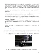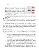
travels through a flow control device (7) which adjusts its flow in increments of 25%, 50%, 75% or 100% and
finally to the cone or backsweep. The flow control device (7) can be adjusted through the printer driver
settings. The cone path protects the focus lens (8) and provides a downward flow directly into the beam path
at the focus point of the laser beam. You choose which source (Gas or Air) (5 or 6) to use through the printer
drivers’ settings. If you choose to use a gas to supply the cone, the supply must go through the GAS coupling
(9).
As the diagram indicates, the optics protection path is not regulated nor solenoid valve controlled. So when
the ULS computer Controlled Compressed Air Unit is on air will always flow to the optics to reduce
contamination.
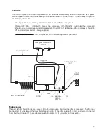
When the ULS computer Controlled Compressed Air Unit is in auto mode and you press the “Start” button on
the laser system, the Air Assist control box will turn ON the ULS computer Controlled Compressed Air Unit
and will keep the ULS computer Controlled Compressed Air Unit ON until the file completes.
The control box also has built in pressure sensors that will detect insufficient supply pressure and will stop
laser processing. An error message, “The air pressure is low or unstable” will appear on the computer
monitor, indicating that there is a problem with your supply of air or gas.
Air Flow Setting Guidelines
As a rule of thumb the flow rate should be set as low as possible for the application especially when using
gas. Start with low flow and adjust upward until the desired result is achieved, such as suppression of flame
up.
Maintenance
The components of the computer controlled air assist are maintenance free. However, use of air assist may
cause the interior of the laser system to become dirty faster. Keep you laser system clean for best
performance.
Air Assist Back Sweep
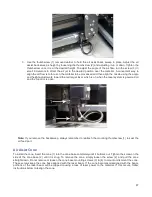
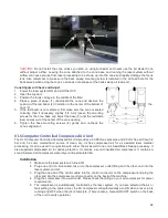
The Air Assist Back Sweep directs debris and smoke away from cutting or engraving process toward the exhaust
at the back of the laser system. When using the air assist back sweep, you can adjust the angle of the air jet
coming from the back sweep as necessary to optimize the effect of the air assist.
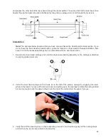
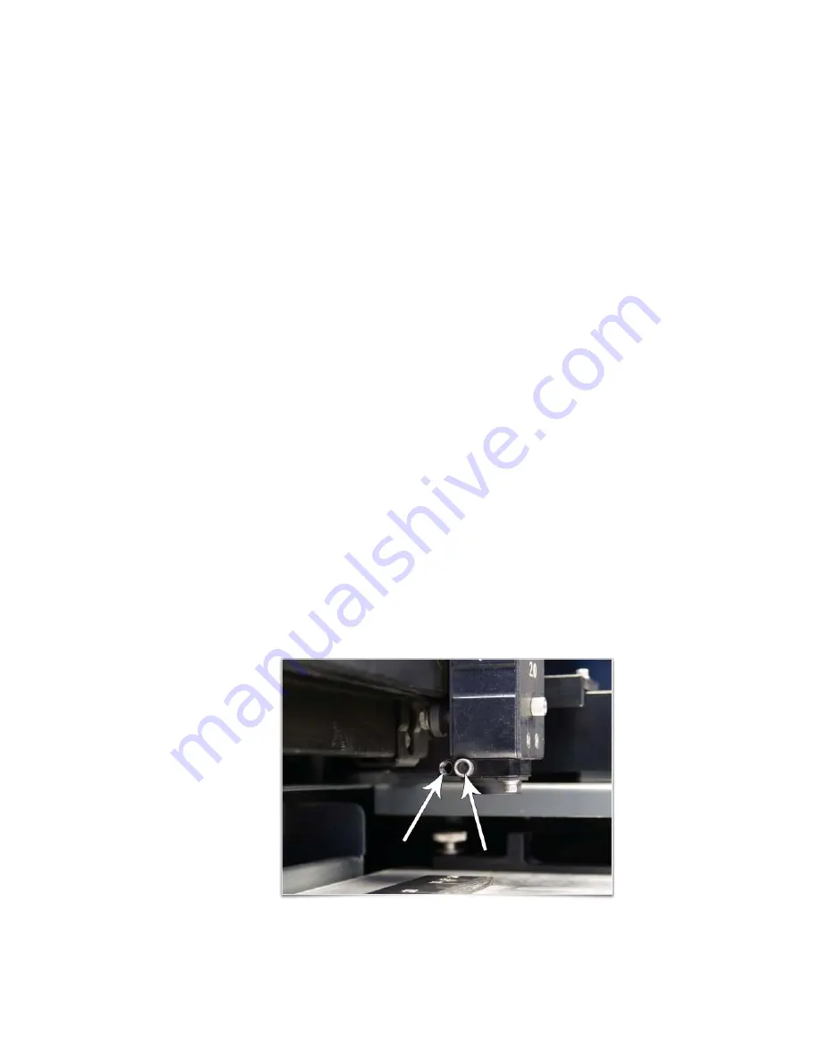
1. To install the back sweep remove the thumbscrew that seals the air assist feed port for the
backsweep.
2. Insert the air assist back sweep’s brass tube into the forward of the two holes on the carriage.
86
Содержание PLS4.75
Страница 1: ...PLS User Guide PLS4 75 PLS6 75 PLS6 150D PLS6MW www ulsinc com Revision August 2012...
Страница 5: ...Chapter 1 Specifications 5...
Страница 8: ...Chapter 2 Safety 8...
Страница 14: ...Tamper Proof Labels Safety Labels...
Страница 15: ...ULS Fiber Laser Cartridge Labels 15...
Страница 16: ......
Страница 17: ...PLS4 Back View 17...
Страница 18: ...PLS6 Front View 18...
Страница 19: ......
Страница 22: ...Chapter 3 Installation 22...
Страница 40: ......
Страница 48: ...Chapter 4 Operation 48...
Страница 83: ...Chapter 5 Accessories 83...
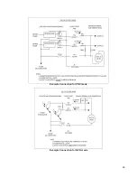
Страница 99: ...Example Connection for PNP mode Example Connection for NPN mode 99...
Страница 111: ...Chapter 6 Maintenance 111...
Страница 119: ...www ulsinc com...

