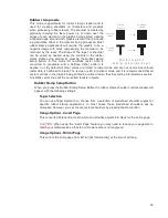
Step 5:
Establish the tuning value.
Once the Contrast, Definition and Density are determined, an easy way to set the tuning
value on a given material at a desired processing speed is to create a graphic consisting
of about 20 thin vertical lines about 1” (25.4 mm) tall and .010” (.254 mm) apart in the
center of the engraving field. The lines should have a line thickness of .001” (.0254 mm) if
possible in the graphic application being used, otherwise use the thinnest the application
allows. Then print the graphic to the laser system as a raster image by forcing the color
the lines are drawn in to be in Rast Mode in the color table and the image density to 1
(draft mode). Make sure you set your processing speed equal to the speed at which you
plan to run your application and the laser power set high enough to mark the material.
This will result in vertical lines that look dotted. You can then look at the dots and if they
are not lined up vertically, adjust the tuning value by 1-2 ticks and try again. Repeat until
the dots in the dotted lines are lined up vertically.
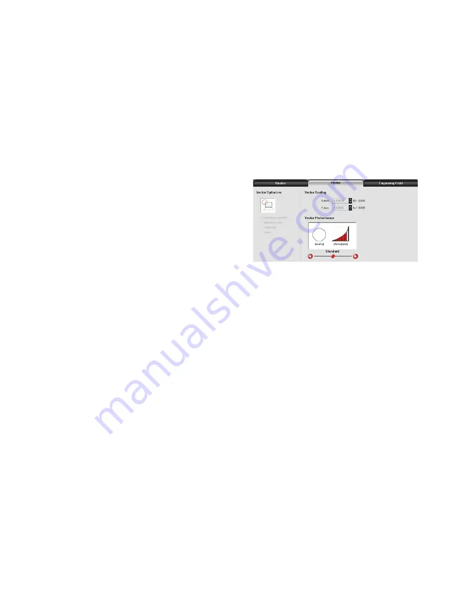
Vector Sub-Tab
The vector sub-tab on the manual control tab of the printer
driver setting interface displays a group of settings which
affect how vector objects are processed by the laser
system. The controls in the sub-tab are described below:
Vector Optimizer
The four available selections apply to vectors and
affect how vectors are grouped and in what order they
are executed. Vectors are grouped by pen color first
and will always execute in the color order listed in the color table, but all vectors of a given color will be
grouped and executed based on which of the following controls is selected:
None
This selection does no sorting or enhancing and prints in the original order in which they were passed to
the printer driver by the graphics program you used to create them. This is usually a random order.
Remember, however, that they will always be grouped by color.
Enhance Only
The ENHANCE function looks for all vectors that are connected in the graphic being printed and makes
them into a continuous path.
Sort Only
The SORT function will sort vectors so they are executed in the following order:
1. All open path vectors are output first, beginning with the end point of the vector path that is closest to
the current position of the focus carriage. All subsequent open vector paths are output using the same
“nearest neighbor” starting point method.
2. Once open paths are completed, closed paths will follow in a nested order, beginning with closed
paths that are contained within other closed paths, with the innermost closed path executed first and
ending with the outermost closed path.
Enhance and Sort
Enhance and Sort turns on both features simultaneously.
Vector Scaling
This feature allows you to calibrate vector output size if necessary for your application. To calibrate the
system, draw a simple shape, such as a square, to a known size and print that shape as a vector object
(make sure line thickness is .001” [.0254 mm] or less). Measure the object vertically and horizontally
using a caliper or other measuring device and use the formula (desired length/measured length) to
determine the scale ratio in X and Y. Enter the result into the X-axis and Y-axis text boxes of the vector
67
Содержание PLS4.75
Страница 1: ...PLS User Guide PLS4 75 PLS6 75 PLS6 150D PLS6MW www ulsinc com Revision August 2012...
Страница 5: ...Chapter 1 Specifications 5...
Страница 8: ...Chapter 2 Safety 8...
Страница 14: ...Tamper Proof Labels Safety Labels...
Страница 15: ...ULS Fiber Laser Cartridge Labels 15...
Страница 16: ......
Страница 17: ...PLS4 Back View 17...
Страница 18: ...PLS6 Front View 18...
Страница 19: ......
Страница 22: ...Chapter 3 Installation 22...
Страница 40: ......
Страница 48: ...Chapter 4 Operation 48...
Страница 83: ...Chapter 5 Accessories 83...
Страница 99: ...Example Connection for PNP mode Example Connection for NPN mode 99...
Страница 111: ...Chapter 6 Maintenance 111...
Страница 119: ...www ulsinc com...

