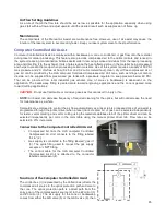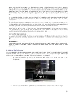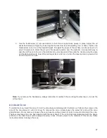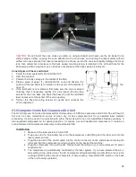
3.
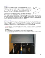
Then connect the other end of the patch cable to the PWR/COM IN RJ9 connector at top of Automation
Kit.
4.
(Optional) If you are using an ULS computer Controlled Compressed Air Unit for air assisted laser
processing, use the included RJ9-to-RJ9 cable to connect the compressor to the unused RJ9 PWR/COM
OUT jack on the automation kit.
97
Содержание PLS4.75
Страница 1: ...PLS User Guide PLS4 75 PLS6 75 PLS6 150D PLS6MW www ulsinc com Revision August 2012...
Страница 5: ...Chapter 1 Specifications 5...
Страница 8: ...Chapter 2 Safety 8...
Страница 14: ...Tamper Proof Labels Safety Labels...
Страница 15: ...ULS Fiber Laser Cartridge Labels 15...
Страница 16: ......
Страница 17: ...PLS4 Back View 17...
Страница 18: ...PLS6 Front View 18...
Страница 19: ......
Страница 22: ...Chapter 3 Installation 22...
Страница 40: ......
Страница 48: ...Chapter 4 Operation 48...
Страница 83: ...Chapter 5 Accessories 83...
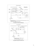
Страница 99: ...Example Connection for PNP mode Example Connection for NPN mode 99...
Страница 111: ...Chapter 6 Maintenance 111...
Страница 119: ...www ulsinc com...


