•
If you would like the laser system to re-home the X and Y axes before it processes each job, select the
‘Home XY Before Engraving’ switch.
•
Your laser system may contain an Air Pressure detection switch to warn you if no air pressure is present
and you have selected air assist functions in the job properties window. If the DETECT AIR PRESSURE
switch is selected and sufficient air pressure is not present, then an error message is displayed. Deselect
this switch to stop these error messages from being displayed.
Diagnostics Tab
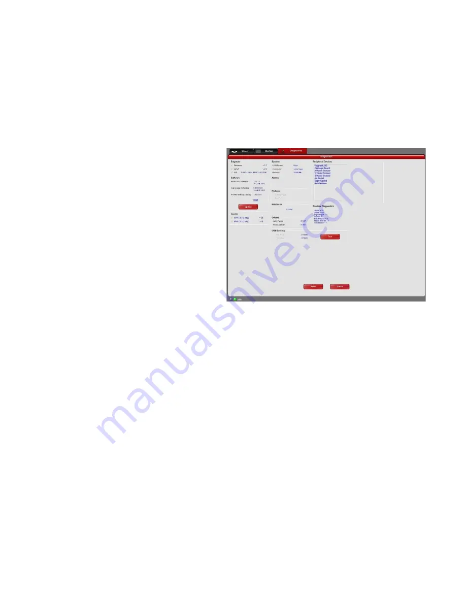
The Diagnostics Tab gives you important information about your laser system for troubleshooting purposes.
The diagnostics tab contains the following:
•
ENGRAVER shows the current Firmware
and FPGA version being loaded in the laser
system. It also displays the Serial Number of
your laser system. The Serial Number is
needed when calling the Customer Service
Team at ULS.
•
SOFTWARE displays the current Materials
Database, Language Database and Printer
driver versions being used.
•
An UPDATE button in the software section
checks the ULS website for the latest
available version of the software and allows
for updating the latest version if desired
(computer must have internet access).
•
PERIPHERAL DEVICES displays the
current firmware version for various devices
installed in the laser system as well as
status information about those devices.
•
LASER displays information about the current laser cartridge(s) installed in the laser system. If a red ‘x’
appears, this indicates that the laser cartridge is either not functioning properly or is disabled because
one of the safety interlocked doors to the laser system is open (causing the interlock system to disable
the laser).
•
The Test button, under USB LATENCY, displays information about the speed of the USB connection.
Typical USB 2.0 performance should be below 10 msec and worst case USB 2.0 performance should be
below 100 msec.
•
SYSTEM displays information about your personal computer.
•
ALARMS shows the status of the over-temperate circuit in the material processing area and indicates if
the Thermal Sensor circuit battery is low in power. If the Thermal Sensor inside the laser system is
triggered, an alarm will sound and the laser will be shut down.
•
FIXTURES indicates if a cutting table is installed on the engraving table and properly detected.
•
INTERLOCKS displays the status of the Top, Front or Rear Doors of the laser system.
•
COMPRESSOR shows the status of the ULS computer Controlled Compressed Air Unit which supplies
compressed air for the air assist feature.
•
The RUNTIME DIAGNOSTICS box is for use when troubleshooting.
•
The PRINT button gathers the information displayed on the Diagnostics Tab into a PDF file. This PDF file
can be emailed to the Customer Service Team at ULS for aid in troubleshooting.
74
Содержание PLS4.75
Страница 1: ...PLS User Guide PLS4 75 PLS6 75 PLS6 150D PLS6MW www ulsinc com Revision August 2012...
Страница 5: ...Chapter 1 Specifications 5...
Страница 8: ...Chapter 2 Safety 8...
Страница 14: ...Tamper Proof Labels Safety Labels...
Страница 15: ...ULS Fiber Laser Cartridge Labels 15...
Страница 16: ......
Страница 17: ...PLS4 Back View 17...
Страница 18: ...PLS6 Front View 18...
Страница 19: ......
Страница 22: ...Chapter 3 Installation 22...
Страница 40: ......
Страница 48: ...Chapter 4 Operation 48...
Страница 83: ...Chapter 5 Accessories 83...
Страница 99: ...Example Connection for PNP mode Example Connection for NPN mode 99...
Страница 111: ...Chapter 6 Maintenance 111...
Страница 119: ...www ulsinc com...

