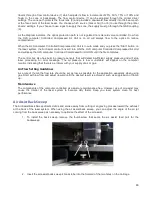
Air Flow Setting Guidelines
As a rule of thumb the flow rate should be set as low as possible for the application especially when using
gas, start with low flow and adjust upward until the desired result such as suppression of flame up.
Maintenance
The components of the Manual Air Assist are maintenance free. However, use of air assist may cause the
interior of the laser system to become dirty faster. Keep you laser system clean for best performance.
Computer Controlled Air Assist
Computer Controlled Air Assist is employed with a backsweep or cone to control air or gas flow onto the material
during laser material processing. This feature also provides compressed air to the optics (mirrors and lenses) in
the system reducing contamination. Air/Gas assist aids in removing smoke and debris from the laser processing
area and directing it to the exhaust. It also helps reduce the heat affected zone in the material being processed
and helps to prevent flame up when processing certain materials. Use of this system requires a supply of 50 PSI
max pressure and 2.0 cfm free air flow (3.2 bar and 3.2 cubic meters/hour), clean, dry oil free compressed air or
gas. Air can be provided by the ULS computer Controlled Compressed Air Unit. Gas, such as nitrogen or carbon
dioxide, can be supplied from pressurized gas tanks with a pressure regulator to keep pressure below 60 PSI.
That can be procured from local industrial gas vendors. Use of cone vs. backsweep is dependent on the
application. The backsweep fitting is geared more toward engraving applications and the cone is geared more
toward cutting applications.
CAUTION:
Do not use flammable or corrosive gases as this can result in injury or fire.
NOTE:
Air Assist can decrease frequency of required cleaning for the optics, but will not decrease the need
for maintenance as a whole.
Solenoids are employed to control the air flow automatically as a laser job is processed. Use of air assist is
programmed through the printer driver when a laser job is created. Air or gas can be selected independently
for raster, vector marking and vector cutting using the materials database tab of the printer driver and can be
selected independently per color in the color table using the manual printer driver tab. Flow rate can be
selected in 25% increments.
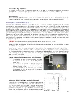
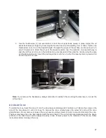
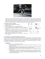
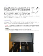
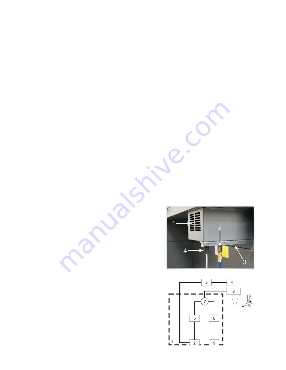
Connections to the Computer Controlled Air Assist
•
Compressed Air from the ULS computer Controlled
Compressed Air Unit connects to the fitting labeled
“air in” (2).
•
Gas supply is connected to the fitting labeled “gas in”
(3). The quick fitting used to connect the gas supply
accepts a ¼ NPT fitting.
•
The control cable for the ULS computer Controlled
Compressed Air Unit is attached to the connector
labeled compressor (4).
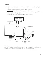
Functions of the Computer Controlled Air Assist
The control box (1) (represented by the dotted lines) directs the
compressed air source to the optics protection path and also to
the cone. The optics protection path is a direct path from the
entry point of the compressed air source (2) to the #2 mirror (3)
and #3 mirror (4). The air supply for the cone or backsweep
comes from either the AIR valve (5) or the GAS valve (6), then
85
Содержание PLS4.75
Страница 1: ...PLS User Guide PLS4 75 PLS6 75 PLS6 150D PLS6MW www ulsinc com Revision August 2012...
Страница 5: ...Chapter 1 Specifications 5...
Страница 8: ...Chapter 2 Safety 8...
Страница 14: ...Tamper Proof Labels Safety Labels...
Страница 15: ...ULS Fiber Laser Cartridge Labels 15...
Страница 16: ......
Страница 17: ...PLS4 Back View 17...
Страница 18: ...PLS6 Front View 18...
Страница 19: ......
Страница 22: ...Chapter 3 Installation 22...
Страница 40: ......
Страница 48: ...Chapter 4 Operation 48...
Страница 83: ...Chapter 5 Accessories 83...
Страница 99: ...Example Connection for PNP mode Example Connection for NPN mode 99...
Страница 111: ...Chapter 6 Maintenance 111...
Страница 119: ...www ulsinc com...


