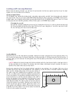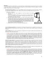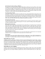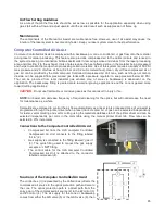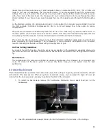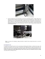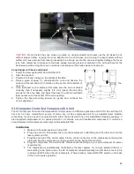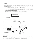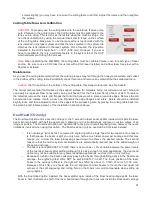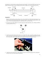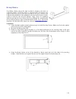
screws slightly (you may have to remove the cutting table to do this). Adjust the rulers and then retighten
the screws.
Cutting Table Focus Lens Calibration
CAUTION:
To properly use the cutting table with the autofocus feature or the
auto Z feature in the printer driver, the Cutting table must be calibrated to the
lens you are using. This is done at the factory when the machine ships. You
can check calibration by using the manual focus tool to focus on the surface
of the cutting table. Make sure to use the manual focus tool included with the
lens installed in the laser system and that the lens selected in the system tab
matches the lens installed in the laser system. Once focused, the Z position
indicated in the UCP should be 0” +/-.020” (.508 mm). However, if you ever
have to recalibrate, there is a calibrate feature in the system tab of the UCP
which will walk you through the process.
Note:
When calibrating the PLW6MW, the cutting table must be calibrated twice, once for each type of laser
source. Be sure to use a CO2 laser focus tool with a CO2 laser installed, and a fiber laser focus tool with a
fiber laser installed.
Maintenance
As you use the cutting table material from the cutting process may fall through the honeycomb surface and collect
in the bottom of the cutting table. Periodically check this area and remove any material that has collected there.
Caution:
If left to build up in the bottom of the cutting table, this scrap material can be a fire hazard.
The honeycomb material that makes up the support surface for materials being cut will wear out over time and
can easily be replaced. New honeycomb can be purchased from the Customer Service Team at ULS. To replace
the material, remove the rulers and flanges that hold the honeycomb in place around its edges. Remove the old
honeycomb and replace it with a new one. Reinstall the edge flanges and rulers. Rulers should be installed
slightly loose and then adjusted to match the edges of the processing area by placing the cutting table back into
the machine and following step 7 of the installation instructions above.
Dual Head (CO2 only)
The Dual Head option adds a second carriage to the X axis with a laser beam splitter inside which splits the laser
beam into two beams with half the power each, allowing you to simultaneously engrave or cut two copies of an
image or pattern. The Dual Head option can significantly reduce your overall engraving time, however, there are
limitations involved when using this option. The Dual Head can only be used with a CO2 laser installed.
•
It is not always “twice as fast” compared to engraving with a single head for two reasons. One reason
is that because the beam is split you only have half as much laser power per carriage and this may
require you to slow the laser processing speed down to achieve the desired results. The second
reason is that the motion system accelerations are automatically reduced due to the added weight of
the second carriage.
•
The beam is not split EXACTLY 50/50; there is as much as +/- 5% variation between the power levels
of the two laser beams after splitting. Although it is close enough for most applications, the dual head
option may not be suitable for very power sensitive applications, such as cloth or vinyl cutting.
•
Because of a shift in the beam caused by passing the beam through splitting optics in the Dual Head
carriage, the engraving field WILL NOT be split EXACTLY in half. The focus position of the laser
beam in the carriage furthest to the right will be shifted by about +/- 1/16th of an inch (1.59 mm).
Because of this shift, you should use the red alignment pointer beams to locate the new upper left
corners of the split engraving and cutting field on the X axis ruler and compensate when setting up
your graphics.
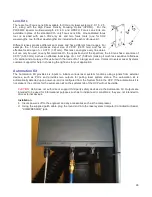
With the Dual Head option installed, the beam splitter optic inside of the Dual head carriage splits the laser
beam in half. It reflects one half of the laser beam down through the focus lens inside the Dual Head carriage
91
Содержание PLS4.75
Страница 1: ...PLS User Guide PLS4 75 PLS6 75 PLS6 150D PLS6MW www ulsinc com Revision August 2012...
Страница 5: ...Chapter 1 Specifications 5...
Страница 8: ...Chapter 2 Safety 8...
Страница 14: ...Tamper Proof Labels Safety Labels...
Страница 15: ...ULS Fiber Laser Cartridge Labels 15...
Страница 16: ......
Страница 17: ...PLS4 Back View 17...
Страница 18: ...PLS6 Front View 18...
Страница 19: ......
Страница 22: ...Chapter 3 Installation 22...
Страница 40: ......
Страница 48: ...Chapter 4 Operation 48...
Страница 83: ...Chapter 5 Accessories 83...
Страница 99: ...Example Connection for PNP mode Example Connection for NPN mode 99...
Страница 111: ...Chapter 6 Maintenance 111...
Страница 119: ...www ulsinc com...

