12
SECTION 2
IDENTIFICATION AND FUNCTION
2.4.2 Cooling Fan
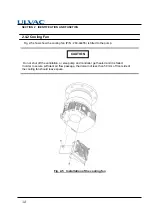
Fig. 2-5 shows how the cooling fan (P/N : 263-44455) is fitted to the pump.
Do not shut off the ventilation, or else pump and controller get heated and it is failed.
In order to secure sufficient air flow passage, the domain of less than 50 mm of front side of
the cooling fan should leave space.
Fig. 2-5
Installation of the cooling fan
CAUTION
Содержание UTM300B
Страница 8: ...vii Location of label...
Страница 11: ...x This page is intentionally left blank...
Страница 17: ...xvi Table of contents This page is intentionally left blank...
Страница 30: ...CONSTRUCTION AND PRINCIPLE 3 1 Pump Construction 3 2 Principle of Turbo Molecular Pumping 3 3 Control system 3...
Страница 51: ...34 SECTION 5 INSTALLATION This page is intentionally left blank...
Страница 70: ...GAS PURGE 7...
Страница 77: ...60 SECTION 8 TURBO MOLECULAR PUMP RECONDITION This page is intentionally left blank...
Страница 111: ...A 26 Appendix A COMMUNICATIONS This page is intentionally left blank...
Страница 113: ...This page is intentionally left blank...

