background image

80

 UBI EasyCoder 501 – Technical Manual

ELECTRONICS, cont'd.

RAM Memory

Real-time Clock Circuit

Fuse

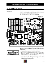
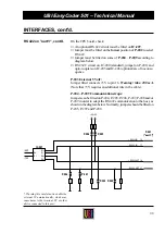
IC-106, IC-107, IC-108 and IC-109

In these sockets either two or four SRAM

1

 packages, which contain

the printer's working and storage memory, can be fitted. The SRAM
packages must have an access time of max. 120 ns and be fitted in
couples (first couple on IC-106 and IC-107, second on IC-108 and
IC-109).

All SRAM packages must be of the same type and size:
• 2 

×

 128 kbyte (1 Mbit) = 256 kbyte (2 Mbit)

• 4 

×

 128 kbyte (1 Mbit) = 512 kbyte (4 Mbit)

• 2 

×

 512 kbyte (4 Mbit) = 1.024 kbyte (8 Mbit)

• 4 

×

 512 kbyte (4 Mbit) = 2.048 kbyte (16 Mbit)

The size of the SRAM's is automatically defined by the printer.

The RAM memory is battery backed-up to avoid loss of data when
the printer is turned off or if the power fails. The NiCd-accumulator
is automatically recharged when the power is on. After having
installed the printer, leave the power on overnight to allow the
battery to become fully recharged. If the printer is kept turned on
less than full working hours, it is recommended to leave the power
on overnight at least once a week. Do not leave the printer off for
several weeks (e.g. during holidays) without having made a full
memory backup on a computer disk.

IC-20

The optional real-time clock circuit (RTC) contains a clock/
calendar with battery backup. When an RTC is fitted on IC-20, the
time and date do not have to be set manually each time the printer
is started. (See 

TIME$

 and 

DATE$

 in the UBI Fingerprint manuals

or in the UBI Direct Protocol Programmer's Guide).

When installing an RTC, be careful to fit it with the semi-circular
marking pointing upward, as seen when the CPU board is fitted in
the printer. Because of the risk of short-circuits, do not use any
conductive tools when fitting or removing the RTC.

FY-300

The CPU board contains components for transforming the mains
current into the various voltages required by the logics and the
printhead. The CPU board is protected by a fuse situated at the lower
left corner of the board.

Never replace a blown fuse without having found and remedied the
fault, that caused it to blow. That usually requires the assistance of
a skilled service technician.

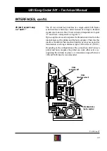
WARNING!

The semicircular “front” marking of

each package should face upward as

seen when the CPU board is fitted

in the printer.

If a RAM package is fitted upside

down, the recharging of the CPU

board's battery backup could be

damaged. This will eventually cause

memory loss.

1

/. SRAM is an abbreviation for Static

Random Access Memory.

Содержание EasyCoder 501

Страница 1: ...edia Type 28 Print Defines 28 Performance 30 Memory Allocation 31 Setting Up EasyCoder 501 Different Methods 32 Setting Up General Information 33 EasyCoder 501 E 501 SA Entering the Setup Mode at Inst...

Страница 2: ...g a Memory Card 63 Removing a Memory Card 63 Label Taken Sensor General Information 64 Adjusting the Sensitivity 65 Program Example 66 Paper Cutter General Information 67 Controlling the Cutter 68 Cle...

Страница 3: ...terfaces Communication Port uart1 83 Optional Interface Boards 84 RS 232C V24 on uart1 85 RS 422 on uart1 86 20 mA Current Loop on uart1 89 Serial Interface Board 92 RS 422 485 Interface Board 95 Para...

Страница 4: ...num rique n met pas de bruits radio lectriques d passant les limites applicables aux appareils num riques de classe A prescrites dans le r glement sur brouillage radio lectrique dict par le Minist re...

Страница 5: ...wtoloadthetransferribbon UBI Shell Standard and UBI Shell Enhanced Startup Manuals GivesinformationonhowtoruntheUBIShellstartupprogramin EasyCoder 501 and EasyCoder 501 E respectively EasyCoder 501 Se...

Страница 6: ...utline fonts in TrueType and Speedo formats to be used In addition to the selection ofSpeedofonts included in the package an ever increasing number of standard outline fonts from major distributors be...

Страница 7: ...kbytes Max 2 Mbytes2 256 kbytes Label and Ribbon End Sensors Standard Mains Voltage switch change over 115 230 VAC 10 15 2 6 1 3 A 60 50 Hz Max Power Consumption 300 W Communication Interface standar...

Страница 8: ...also allows you to create your own programs As an option the EasyCoder 501 Ecan be fitted with a special firmware package that allows scalable outline fonts in TrueType and Speedo formats to be used...

Страница 9: ...nsumption 300 W Communication Interface standard RS 232C Prepared for RS 422 20 mA Current Loop 1 x Centronics Interface 2 5 Optional Yes 1 x RS 232C 1 x RS 232C 20 mA CL Interface2 5 Optional Not inc...

Страница 10: ...of label texts and formats The printer is available with either 8 dots mm or 11 81 dots mm printhead density Externally this model is distinguished by its large alphanumeric full ASCII keyboard The f...

Страница 11: ...age switch change over 115 230 VAC 10 15 2 6 1 3 A 60 50 Hz Max Power Consumption 300 W Communication Interface standard RS 232C Prepared for RS 422 20 mA Current Loop 1 x Centronics Interface2 5 Opti...

Страница 12: ...the printer to its host computer by means of a suitable communicationcableasdescribedlaterinthischapter Referto the chapter Interfaces for more information on computer connectionandcableconfiguration...

Страница 13: ...eprinter srearplategivesinformationon Type Article number Serial number Check the printer in regard to possible options ordered Checkthatthemainscordhasapinconfigurationthatwillfitinto a wall socket a...

Страница 14: ...line is preferred If no such line is available avoidlinestowhichelectricmotors refrigeratorsand similar devices are connected The power can be turned on off by means of the main switch situated above...

Страница 15: ...e configuration descrip tions Refertothemanualofthehostcomputerorterminalforinformation on how to connect the other end of the communication cable Computer Connection Hints ForUBILabelShop UBIDirectPr...

Страница 16: ...os formatted memory cards SRAM 2 Printer s RAM memory 3 Non DOS formatted memory cards SRAM or OTPROM 4 Printer s ROM memory e g the configuration EPROM s This implies that if you have a startup file...

Страница 17: ...Refer to the Startup Manual of UBI Shell Standard or UBI Shell Enhanced respectively for further information The digits in the lower right corner of the display indicate the version of UBI Shell C UB...

Страница 18: ...ions Default1 Contrast Variable 0 10 Middle 5 Ser Com2 Baudrate 300 600 1200 2400 4800 9600 19200 384003 9600 Parity even odd mark space none none Charlength 7bits 8bits 7bits Stopbits 1bit 2bits 2bit...

Страница 19: ...ustment of the printoutinregardofblackness e g toadapttheprintertovariations in quality between different batches of the same paper quality The serial communication setup controls the communication be...

Страница 20: ...to the UBI Fingerprint Reference Manual for information on which characters are available in various combinations of character length and character set 7 Characters ASCII 0 127 decimal can be transmi...

Страница 21: ...this protocol the communication is controlled by the special characters ENQ ASCII05dec andACK ASCII06dec beingtransmittedonthesamelineasthe data ThesendingunittransmitsENQatregularintervals Iftherespo...

Страница 22: ...sensor Obviously itisimportantthattheprinterissetupforthecorrecttype of media see Media Type later in this chapter so the firmware can interpret the signals correctly TheLSScanbemovedmax 50mmsideways...

Страница 23: ...ll be pulled back before the printing starts Accordingly theorigoismovedtowardstheforwardedgeofthe copy This has the same effect as a negative FORMFEED before a PRINTFEED The Stop Adjustment is set up...

Страница 24: ...o decide the amount of paper feed when using fix length strip To set an emergency stop which works when the printer is set up for Label w gaps Ticket w mark or Ticket w gaps IftheLSShasnotdetectedagap...

Страница 25: ...imum print width is 104 mm 4 1 and the maximum web widthis120mm 4 7 thisleavesamarginofatleast16mm 0 6 along the outer edge of the web where no printing can be per formed Print Window 8 dots mm 203 2...

Страница 26: ...is leaves a margin of at least 13 mm 0 51 along the outer edge of the web where no printingcanbeperformed Furthermore ifan110mm 4 33 wide web is used the printhead will be centre aligned with a 3 mm 0...

Страница 27: ...ce the maximum printwidthis108 3mm 4 26 andthemaximumwebwidthis120 mm 4 7 this leaves a margin of at least 10 9 mm 0 43 along the outer edge of the web where no printing can be performed Print Window...

Страница 28: ...indicates that the last ordered label or ticket was successfully printed but no more labels tickets can be printed because of an empty paper stock Head Resistance The power to the printhead is adjust...

Страница 29: ...er again CODE39 CODE39 1 234567 890128 618 ohms 8 dots CODE39 CODE39 Test label 1 Test label 2 UART1 BAUDRATE 9600 PARITY NONE CHAR LENGTH 7 STOPBITS 2 RTS CTS DISABLE ENQ ACK DISABLE XON XOFF DATA FR...

Страница 30: ...er 501 E EasyCoder 501 SA 8 dots mm 203 2 dpi Thermal Transfer Printing GP HP Ribbon Performance Text Printing Hor bar code Vert bar code Normal 100 mm s 4 s 100 mm s 4 s 100 mm s 4 s High 200 mm s 8...

Страница 31: ...o set the size for three kinds of memory buffers The ImageBufferstorestheprintoutimagebeforeprintingand during batch printing To ensure that high print speed is sus tained during the printing of deman...

Страница 32: ...eterscanbechangedfromwithinUBILabelShop and for the UBI Windows Driver from Control Panel Printers in Microsoft Windows B EasyCoder 501 with UBI Shell You can change any setup parameter via the Termin...

Страница 33: ...de which allows it to be set up in regard of all parameters by means of its own keyboard The Setup Mode can be accessedviatheUBIShellEnhancedprogram bytheissuingofthe UBIFingerprintstatementSETUP orby...

Страница 34: ...Turn on the power Whenthedisplayshowsthemessage Enter UBIShell xsec press Enter Pressthe Setup key thisfacilitycanbeusedanywherewithin UBI Shell Enhanced Set up the printer as described in this chapt...

Страница 35: ...he contrast 1 step or the LSS 10 steps Used to move down between menus to scroll forward between options in stacks and to increase the value of the contrast 1 step or the LSS 10 steps Used to exit the...

Страница 36: ...FEEDADJ FEEDADJ STARTADJ STARTADJ 0 FEEDADJ STOPADJ STOPADJ 0 SETUP SERVICE Enter Enter If an optional interface board with at least one serial channel is fitted communication setup menus for each of...

Страница 37: ...PAPER TYPE designation designation PAPER TYPE designation PRINT DEFS TESTPRINT PRINT PRINT C EXIT ULTRA HIGH HIGH SERVICE PERFORMANCE PERFORMANCE NORMAL SERVICE MEMORY ALLOC MEMORY ALLOC IMAGE BUFF SI...

Страница 38: ...Return to higher level C Clear Acknowledge option and proceed Enter Enter ThedetectionpartoftheSetupModeisusedforadjustingthelabel stop sensor and to control the paper feed Label stop sensor LSS LABEL...

Страница 39: ...de of the menu LABEL 103 GAP Put a piece of backing paper without any label into the sensor The cursor should move to the centre of the menu LABEL 103 GAP Finallyremoveallpaperwebfromthesensor Thecurs...

Страница 40: ...eases the level 1 step F4 or decreases the level 10 steps F5 or increases the level 10 steps Keep trying until you find the right level When the adjustment looks right press Feed This will produce a T...

Страница 41: ...d operation Feed Feed Acknowledge setup and proceed Enter Enter Feed adjustment STARTADJ 0 The present value of the start adjustment is displayed within brackets Accept the value by pressing Enter or...

Страница 42: ...Enter Service Enter Enter Enter password 1138 Enter 1138 Enter Return to Contrast menu F5 Exit Setup Mode Setup Save Three menus will successively be displayed In each menu the current setup value is...

Страница 43: ...sured value is displayed within brackets Action EasyCoder 501 E EasyCoder 501 SA Proceed Enter Enter Paper Type A number of direct thermal paper and thermal transfer ribbon designations are displayed...

Страница 44: ...NT C EXIT Action EasyCoder 501 E EasyCoder 501 SA Print a new Test Label Print Print Check status F5 Exit and proceed C or Enter Clear or Enter Check status reports five possible error conditions Prin...

Страница 45: ...r 501 E EasyCoder 501 SA Enter new value numeric keys numeric keys Acknowledge and proceed Enter Enter The memory allocation menus conclude the Setup Mode Press C or Clear toreturntothemainMemoryAlloc...

Страница 46: ...the printer is fitted with a special mechanism in which a special ink coated transfer ribbon is fed between the printhead and the receiving face material e g plain paper When the ribbon is heated by...

Страница 47: ...ad pressure Direct thermal printing requires more pressure than thermal transfer printing Do not use more pressure than necessary since it may reduce the life of the printhead and in case of thermal t...

Страница 48: ...y wear of the printhead The pressure is factory adjusted but special applications or a change between printing methods may require readjustment using thetrial and errormethod Donotusemorepressurethann...

Страница 49: ...h adjustment like this Turn both adjustment knobs clockwise as far as they go to maximum pressure Release the pressure of the inner spring package by turning the knob 2 1 4 turns counter clockwise 9 c...

Страница 50: ...heribbonbecomeswrinkled afewchecksshouldbeperformed before the guide plate is readjusted Is the printhead pressure properly adjusted Is the green paper guide ring correctly positioned Is there anythin...

Страница 51: ...k print but that does not affect the calculation of distances sizes and positions The8dots mm 203 2dpi printheadcontains832dots whichgives a maximum print width of 104 mm 4 095 The 11 81 dots mm 300 d...

Страница 52: ...lity of bar codes be impaired by an inappropriate background colour but the pre print ink may also be too opaque or have such an insulating effect that the legibility of text will be insufficient Make...

Страница 53: ...hlyreadableanddefinedprintoutonmost face materials with smooth surfaces It has a good smear resistance and is most suitable for intricate logotypes and images on Matt Coated Transfer Supreme face mate...

Страница 54: ...ermore the New Supplies setup parameter allows addi tionaloptionstobeselectedbya13 digitcode Onceselected itcan bereselectedasa PaperType optionusingthefirst4digitsofits code number The first digit in...

Страница 55: ...recommended if preprint or varnishes are used on the thermal paper in connection with these setup options In addition to the standard options above there are some thermal paperwithsimilarcharacteristi...

Страница 56: ...rom the core Else the thermal transfer ribbon may be damaged Roll Max diameter 205 mm 8 07 Max width 120 mm 4 72 Min width 25 4 mm 1 0 Max web thickness 175 m 0 007 see note We recommend that a paper...

Страница 57: ...57 UBI EasyCoder 501 Technical Manual PAPER DIMENSIONS cont d a NON ADHESIVE STRIP a Web Width Maximum 120 0 mm 4 72 Minimum 25 4 mm 1 00 Non Adhesive Strip...

Страница 58: ...4 mm 1 00 The backing paper must not extend more than a total of 1 6 mm 0 06 outside the paper and should protrude equally on both sides b Paper Width excluding backing paper Maximum 118 4 mm 4 66 Mi...

Страница 59: ...th 8 dots mm 1 1875 mm 73 8 Max label length 11 81 dots mm 1 1250 mm 49 2 Min label length all 10 mm 0 39 Max printable length 8 dots mm 1250 mm 49 2 Max printable length 11 81 dots mm 833 mm 32 8 e L...

Страница 60: ...lit Length The length of the detection slit excluding corner radii must be Minimum 5 0 mm 0 20 e Detection Slit End Provided the restrictions of the minimum slit length and slit start are observed the...

Страница 61: ...markmorethan50mm 1 97 from the inner edge of the paper f Black Mark Height Commonly used height 12 5 mm 0 5 Minimum 5 0 mm 0 2 g Black Mark Y Position It is recommended to place the black mark as clos...

Страница 62: ...ram Once programmed they cannot reprogrammed SRAMcardsmaybeusedthesamewayasOTPROMcards The filesinsuchacardareregardedasanintegratedpartoftheprinter s ROMmemoryandcanbelistedusingthestatementFILES rom...

Страница 63: ...w Makesurethatthemanufacturer slogotypeonthememorycard is facing upwards Press firmly inwards so the pins in the adapter engage the corresponding slots in the memory card Turn on the power again and c...

Страница 64: ...utter The label taken sensor consists of a photoelectric sensor with a bracket and a connection cable The sensor is fitted inside the front door see illustration below The photoelectric sensor emits a...

Страница 65: ...sing the PRSTAT function also see UBI Fingerprint manuals Here is an example on how such a program can be made 10 BREAK 1 88 20 BREAK 1 ON 30 ON BREAK 1 GOSUB 1000 40 FORMFEED 50 IF PRSTAT AND 2 THEN...

Страница 66: ...nting of a ten label batchprintingjob Anewcopywillnotbeprinteduntilthepending label has been removed FONT SW030RSN PRTXT HELLO LTS ON PRINTFEED 10 InUBIFingerprintversionsearlierthan6 0 thestatusofthe...

Страница 67: ...ded to cut through continuous non adhesive paper strip or through the backing paper between labels Itmustnotbeusedtocutthroughanykindofadhesive whichwould stick to the cutting parts and rapidly render...

Страница 68: ...mm 1 5 in front of the printer s dot line The paper feed should be adjusted accordingly see Setup Parameters Detection earlier in this manual Should you inadvertently have cut through self adhesive w...

Страница 69: ...usedtoindicatepaper lowandribbon low conditions as opposed to out of paper out and out of ribbon con ditions which are supported by the standard error handling See SYSVAR inUBIFingerprintmanualsorinth...

Страница 70: ...ed see Ribbon Save Control below When the software determines that no printing is to be performed within the next20mm 0 8 ormoreofpaperfeed theprintheadisliftedby a motor and the transfer ribbon is st...

Страница 71: ...Direct Protocol Programmer s Guide There are no adjust ments available to the operator WhentheprinterisfittedwithaRibbonSaveDevice thatisturned offbymeansofaRIBBONSAVEOFF instruction itisrecommended n...

Страница 72: ...y means of a screw protruding through the outer lower gable Turning the screw clockwise will move the LSS inwards and vice versa The position of the LSS in relationtothepaperisbestcheckedbylookinghead...

Страница 73: ...e out Both guide plates are provided with seemingly opaque smooth windows which actually are transparent to the light of the LSS These windows must be kept clean from dust stuck labels and adhesive re...

Страница 74: ...original Speedo and True Type products from UBI Products from other suppliers might work but the functionality cannotbeguaranteed norisanysupportgiven by UBI The UBI Fingerprintstatement FONT converts...

Страница 75: ...2C with the same communication parameters and connect the computer to the communication port uart1 of the printer Check that the communication works both ways by typing e g BEEP on the computer The pr...

Страница 76: ...tream Swiss 721 0003 Roman UBI0005 SPD Bitstream Swiss 721 0005 Bold UBI0010 SPD Bitstream Swiss 721 0010 Bold Condensed UBI0011 SPD Bitstream Dutch 801 0011 Roman UBI0013 SPD Bitstream Dutch 801 0013...

Страница 77: ...the printer and disconnect the power cord The CPU board contains power supply circuits with dangerous voltage Remove the four T10 Torx screws situated along the lower edge of the cover plate as indica...

Страница 78: ...rdcontainsanumberofjumpersandsocket mounted circuits which decide how the printer will work The illustration shows the CPU board 1 040700 30 Before touching the CPU board carefully read the following...

Страница 79: ...nerators1 UPC EAN bar code interpretation fonts Standard fonts SW030RSN 1 and SW030RSN 2 2 Setup options for direct thermal paper and thermal transfer ribbon see the chapter Selecting Paper Ribbon Uti...

Страница 80: ...s without having made a full memory backup on a computer disk IC 20 The optional real time clock circuit RTC contains a clock calendar with battery backup When an RTC is fitted on IC 20 the time and d...

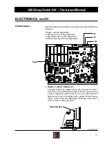
Страница 81: ...sensor LSS adjustment Label taken sensor LTS adjustment Ribbon end sensor R End adjustment Display Contrast Adjustment This potentiometer is situated close to the connector of uart1 andcanbeaccessedt...

Страница 82: ...s of fitting or removing a strap on P 607 strap fitted increased intensity Ribbon End Sensor Adjustment The ribbon end sensor is situated at the rear part of the printing mechanism It emits a narrow b...

Страница 83: ...itable cable can be procured locally and if necessary be modified according to the pinout descriptions in this chapter NOTE A shielded communication cable is required in order to comply with the FCC D...

Страница 84: ...IN SWEDEN Type Art No Ser No 115 230 V 2 6 1 3 A 50 60 Hz TA 1 36 p Centronics connector 230V 0 MADE IN SWEDEN Type Art No Ser No 115 230 V 2 6 1 3 A 50 60 Hz TA 2 DB25 connectors 230V 0 MADE IN SWEDE...

Страница 85: ...as standard Jumper must be fitted on uppermost position of P 202 RS 422 circuit on IC 207 opto couplers on IC 205 and IC 206 optional and straps on P 204 P 209 are of no consequence The following har...

Страница 86: ...CTS1 in 5 5 CTS in DSR in 6 6 DSR in Signal GND 7 7 Signal GND not used 8 15 8 25 not used 5V 16 not used 17 19 DTR out 20 not used 21 25 To Printer uart1 To IBM AT DB25 female connector cable DB9 fe...

Страница 87: ...0metres 4 000 ft by use of a four wire cable The transmission is full duplex i e reception and transmission can take place simultane ously RS 422 requires an additional circuit and a number of straps...

Страница 88: ...itted connects 5V to pin 16 Warning Max 200 mA Note that 5V requires an additional wire in the cable P 204 P 209 Communication straps JumperscanbefittedonP 204 P 205 P 206 P 207 P 208and or P 209 in o...

Страница 89: ...printer and the host computer Therefore this interfaceissuitablewhereelectricalinterferencemayoccur andfor transmission over longer distances up to 500 metres or 1 500 ft Depending on the configurati...

Страница 90: ...0 are of no consequence P 203 External 5 Volt Jumper fitted connects 5V to pin 16 Warning Max 200 mA Becarefulnottoenabletheexternal5Vunintentionally whichmay cause harm to the terminal PC or other de...

Страница 91: ...in 12 Pin 10 Pin 18 Pin 25 TXD TXD RXD RXD Printer active transmitter active receiver Printer active transmitter passive receiver F5 F4 F3 F1 F1 C 0 Enter 3 2 1 Feed 6 5 4 SetUp 9 8 7 Pause Print Prin...

Страница 92: ...e factory installed With the Serial Interface Board installed the following types of interfaces can be selected uart1 Fitted on printer s CPU pcb RS 232C Standard RS 422 or 20 mA CL Option Additional...

Страница 93: ...raps for controlling the RS 232C interface on uart2 Communication Port uart3 RS 232C StrapfittedonP 3 betweenpin1 2 rightandmiddlepins selects RS 232C 20 mA Current Loop Strap fitted on P 3 between pi...

Страница 94: ...to printer 4 RTSA RTSB RS 232C RS 232C RTS from printer 5 CTSA CTSB RS 232C RS 232C CTS to printer 6 DSRA DSRB RS 232C RS 232C DSR to printer 7 GNDI GNDI RS 232 C RS 232C Signal ground 8 not used 9 2...

Страница 95: ...callyinsulatedfromtheprinter in order to avoid electrical interference The RS 422 485 Interface Board may either be bought separately as a kit complete with installation instructions or be factory ins...

Страница 96: ...is half duplex i e transmission and reception cannot take place simultaneously Simplified example of an RS 485 connection A transmission of data can be addressed to a certain unit in an RS 485 multi...

Страница 97: ...RS 422 P 8 and P 9 should be strapped on both units RS485 P 8andP 9shouldbestrappedon master unit Usually the host computer is master P 10 100 terminatingresistor Shouldbestrappedonthefirst and last u...

Страница 98: ...ohm P 10 P 8 P 2 P 9 VEE GNDE PRINTER PRINTER PRINTER master RS 485 MULTIDROP LOOP w printer as master unit Screened twisted 2 line cable approx 50 pf m P 8 and P 9 strapped on master unit P 10 strapp...

Страница 99: ...5 6 7 GNDE Interface ground 8 9 10 11 12 13 14 15 RS422 IN RS 422 only 16 17 RS422 IN RS 422 only 18 19 RS422 OUT RS 422 485 20 21 RS422 OUT RS 422 485 22 23 24 25 STRAP S1 S2 S3 S4 S5 Address 0 Addre...

Страница 100: ...wing types of interfaces can be selected uart1 Fitted on printer s CPU pcb RS 232C Standard RS 422 or 20 mA CL Option Additional circuits required centronics Fitted on Parallel interface pcb Centronic...

Страница 101: ...or other device connected to this port Busy Signal S1 Jumper fitted BUSY signal on until end of ACK signal Nojumperfitted ACK afterBUSY signal asonprevious versions of this board S2 S31 Jumper fitted...

Страница 102: ...2000 1000 BUSY4 1010 RETURN 2000 READY4 2010 RETURN Also see BUSY and READY statements and PRSTAT function in the UBI Fingerprint manuals INTERFACES cont d Parallel Interface Board cont d Pin Signal D...

Страница 103: ...tely as a kit complete with installation instructions or be factory installed With the Industrial Interface Board installed the following means of communication becomes available uart1 Fitted as stand...

Страница 104: ...able this option unintentionally which may cause harm to the connected terminal computer or other device IN OUT connector In Out port 201 204 One relay for each port switches the OUT signal to high or...

Страница 105: ...03 7 GNDI Signal ground 7 OUT 204 8 not used 8 OUT 204 9 not used 9 IN 101 See example below 10 not used 10 IN 101 11 not used 11 IN 102 12 not used 12 IN 102 13 not used 13 IN 103 14 not used 14 IN 1...

Страница 106: ...106 UBI EasyCoder 501 Technical Manual NOTES...

Отзывы: