


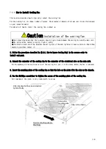


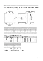


142
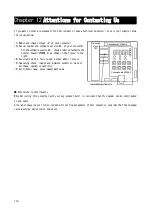
12. Press the [SET] key.
・
The converter mode name is displayed.
Indicating the converter mode "PWM sine wave
mode"
13. Use the keys [
↑
] or [
↓
] to display a desired converter mode, and then press the [SET] key.
・
The converter model is displayed.
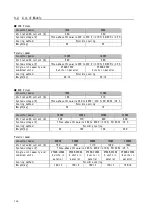
"22" indicates the 200 V class.
14. Use the keys [
↑
] or [
↓
] to display a desired converter model, and then press the [SET] key.
・
DC voltage is displayed.
15. Press the [
→
] key to blink required digits, press the keys [
↑
] or [
↓
] to change numbers to a value measured
by the voltage meter or the tester, and then press the [SET] key.
・
"init" is displayed for a few seconds, and then "End" is
displayed. Now the initialization of the converter is
completed.
・
About five seconds later, the converter series name is
displayed.
・
Then, contents similar to what are displayed at power-on are
displayed. Refer to {4.2.2. What Are Displayed at Power-on}.
・
Then, a monitor item is displayed for about one second, and its
data is displayed.
16. Turn off the converter, and open the front cover.
17. Remove the installed DC voltage meter or tester.
18. Close the front cover.
Adjustment of various inputs
●
After replacing the control board <VFC66R-Z>, be sure to adjust the AC voltage detection adjustment gain:
n-05 according to {5.3.11. Area n}.
●
Before using the analog input/output after replacement of the control board <VFC66R-Z>, be sure to adjust
the analog input/output gain and offset.
●
For how to adjust the analog input/output gain and offset, refer to {5.4.4. Analog Input (2) and (3) Gain
and Offset Adjustment} through {5.4.5. Analog Output (2) and (3) Gain and Offset Adjustment}.


