MAINTENANCE MANUAL
79
STE 85357
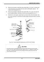
5)
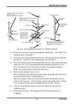
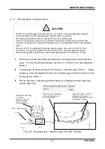
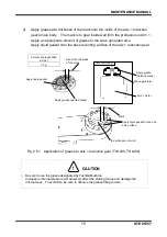
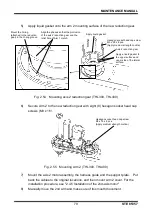
Apply liquid gasket onto the arm 2 mounting surface of the new reduction gear.
Fig. 2.54 Mounting axis 2 reduction gear (THL300, THL400)
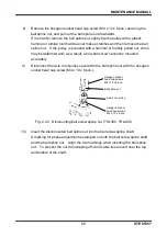
6)
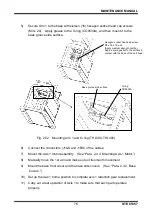
Secure Arm 2 to the new reduction gear with eight (8) hexagon socket head cap
screws (M3 x 16).
Fig. 2.55 Mounting Arm 2 (THL300, THL400)
7)
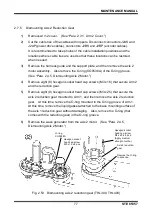
Mount the axis 2 motor assembly, the harness guide and the support plate. Put
back the cables to the original locations, and then mount Arm 2 cover. For the
installation procedure, see "2.4.5 Installation of the 2nd-axis motor"
8)
Manually move the 2nd arm and make sure of its smooth movement.
Hexagon socket head cap screw
M3 x 16 x 8 pcs.
(Apply medium strength Loctite.)
Apply liquid gasket.
Hexagon socket head cap screw
M3 x 25 x 8 pcs.
(Apply medium strength Loctite.)
Axis 2 reduction gear
Mount the O-ring
(attached to the reduction
gear) in the O-ring groove.
Align the phases so that the protrusion
of the axis 2 reduction gear and the
relief hole of Arm 1 match.
Apply a liquid gasket to
the upper surface and
upper side of the lateral
surface.

