


MAINTENANCE MANUAL
109
STE 85357
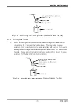
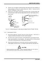
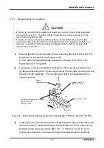
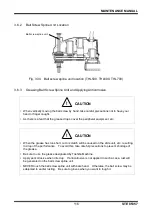
Note that if the ball screw nut is pulled out of the shaft, the ball falls off from the
ball screw nut and, consequently, the ball screw spline unit can no longer be
used.
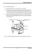
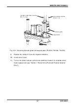
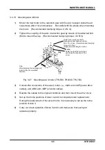
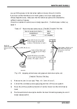
5)
Disconnect the axis 3 timing belt.
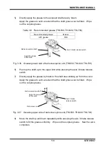
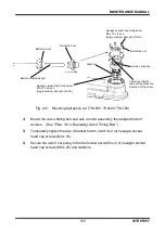
Fig. 3.29 Replacing axis 3 timing belt (THL500, THL600, THL700)
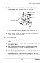
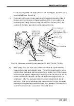
6)
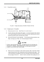
Mount the new timing belt. Insert the ball screw spline shaft into the ball spline
nut, and mount the stoppers. (For the insertion of the ball screw spline shaft,
see “Para. 3.6.5, Mounting Ball Screw Spline Unit.”)
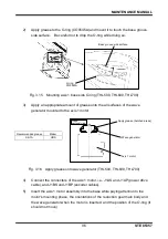
7)
Hang the timing belt to the axis 3 motor assembly which was previously
removed in 3), and temporarily secure it to Arm 2 with four (4) flange head bolts
(M4 x 10, application of Loctite not necessary). Move the ball screw spline unit
up and down to make it fit in. Apply tension using two (2) axis 3 tension
adjustment bolts (M4 x 16, application of Loctite not necessary).
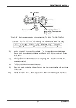
While pulling the axis 3 motor plate with the axis 3 tension adjustment bolts,
measure the tension with a tension meter. Tighten the flange head bolt at the
location where the tension reaches a value slightly smaller than 49 N (because
the tension gets larger by retightening of the flange head bolt). Adjust so that
the tensile value becomes between 49 and 57 N when the flange head bolt is
retightened. Then, secure with the hex nut.
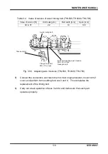
The values to be used for the tension meter are as shown in the table below.
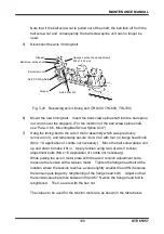
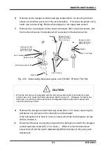
Ball screw spline shaft
Hexagon socket head cap screws
M4 x 16 x 4 pcs.
Axis 4 bracket
Stopper
Stopper
Ball screw nut
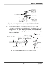
Axis 3 timing belt