MAINTENANCE MANUAL
68
STE 85357
2.6.5
Mounting Ball Screw Spline Unit
!
DANGER
• The ball screw spline unit should be replaced with a new one only after the controller power
supply plug is removed. If the work is done while the power is connected, you may get an
electric shock or the robot may malfunction, which is very dangerous.
!
CAUTION
• Handle the ball screw spline unit with extreme care. If the unit drops or an unusually large
external force is exerted on it, it cannot function any further.
• Replacement of the ball screw spline unit involves mounting and dismounting of Axes 3 and
4 motor assemblies and timing belts. Also observe the cautions on each work.
• Because the motor, timing belt, nut and pulley are disconnected, the mechanical home point
shifts and proper control cannot be done. To avoid this, home return operation of axis 3
and 4 is necessary after replacement of the ball screw spline unit. For the home return
procedures, see “Section 5, Robot Home Point and Position Detector Error.”
• DO NOT pull out the ball screw shaft from the ball screw nut. Otherwise, the ball in the ball
screw nut will drop and the ball screw nut integrated with the ball screw shaft cannot
function any further.
• NEVER touch the ball screw spline unit with bare hand. Otherwise, the ball screw may be
subjected to earlier rusting. Be sure to gloves when you want to tough it.
1)
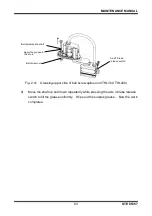
Disconnect the ball spline nut from the new ball screw spline unit.
2)
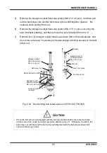
Mount the axis 4 nut pulley on the ball spline nut with the hexagon socket head
cap screws (M4 x 10 x 6 pcs.) and washers.
The bolts are difficult to tighten because the pulley rotates. Thus, tighten them
while holding the pulley with pliers or the likes. In doing so, use a waste cloth
to protect the pulley from scratches.
3)
Mount the ball spline nut on Arm 2 with the hexagon socket head cap screws
(M4 x 12 x 6 pcs.) and washers. When doing so, be careful with the orientation
of the removal tap.

