MAINTENANCE MANUAL
135
STE 85357
5)
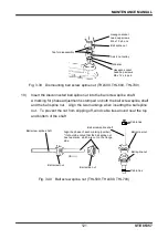
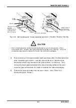
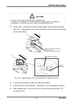
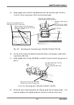
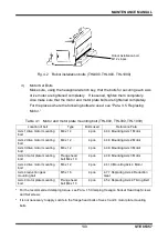
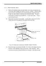
Apply grease to the other O-ring attached to the new reduction gear, and then
mount it in the O-ring groove of the axis 2 reduction gear.
Fig. 3.51 Mounting axis 2 reduction gear (THL500, THL600, THL700)
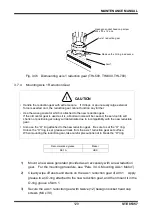
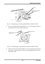
6)
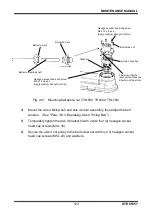
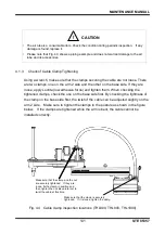
Secure Arm 2 to the new reduction gear with twelve (12) hexagon socket head
cap screws (M3 x 20).
7)
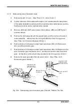
Apply grease to the O-ring (CO0538A), and then mount it in the O-ring groove of
Arm 2.
Fig. 3.52 Mounting arm 2 (THL500, THL600, THL700)
8)
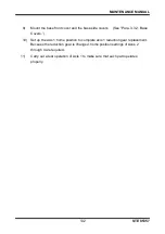
Mount the axis 2 motor assembly, the harness guide and the support plate. Put
back the cables to the original locations, and then mount the arm 2 cover.
Axis 2 reduction
gear
Arm 1
Mount the O-ring (attached to the
reduction gear) in the O-ring groove.
Hexagon socket head cap
screw
M3 x 30 x 12 pcs.
(Apply
medium strength Loctite.)
Align the phases so that the protrusion
of the axis 2 reduction gear and the relief
hole of Arm 1 match.
Mount the O-ring (attached to the
reduction gear) in the O-ring groove.
Hexagon socket head cap screw
M3 x 20 x 12 pcs.
(Apply medium strength Loctite.)
Apply grease to the O-ring (CO0538A),
and then mount it in the O-ring groove.

