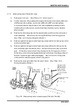
MAINTENANCE MANUAL
74
STE 85357
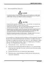
2.7.4
Mounting Axis 1 Reduction Gear
!
CAUTION
• Handle the reduction gear with extreme care. If it drops or an unusually large external
force is exerted on it, the reduction gear cannot function any further.
• Use the wave generator which is attached to the new reduction gear.
If the old center gear is used as it is, abnormal noise will be caused, the service life will
shorten or positioning accuracy will deteriorate due to incompatibility with the new reduction
gear.
• Also use the “O” ring attached to the new reduction gear. Be sure to set the “O” ring.
Unless the “O” ring is set, grease will leak from the axis 1 reduction gear set surface.
When mounting the reduction gear, take careful precautions not to break the “O” ring.
1)
Mount a new wave generator provided as an accessory with a new reduction
gear. For the mounting procedure, see item 1) in
“Para. 2.4.4, Mounting Axis 1
Motor.”)
2)
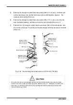
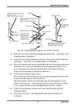
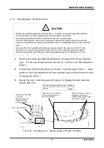
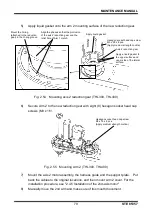
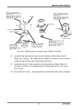
Cleanly wipe off dusts and stains on the axis 1 reduction gear of Arm 1. Apply
grease to an O-ring attached to the new reduction gear, and then mount it in the
O-ring groove of Arm 1.
3)
Secure the axis 1 reduction gear with twelve (12) hexagon socket head cap
screws (M3 x 25).
Recommended anticorrosive Maker
SK-
Ⅱ
HDS
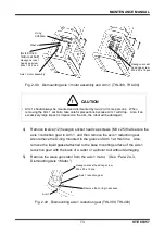
Fig. 2.50 Mounting axis 1 reduction gear (THL300, THL400)
Hexagon socket head
cap screw
M3 x 25 x 12 pcs.
(Apply medium
strength Loctite.)
Mount the O-ring (attached
to the reduction gear) in
the O-ring groove.
Align the phases so that the
protrusion of the axis 1
reduction gear and the relief
hole of Arm 1 match.
Axis 1 reduction gear
Arm 1

