MAINTENANCE MANUAL
113
STE 85357
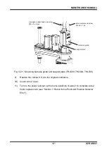
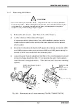
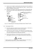
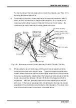
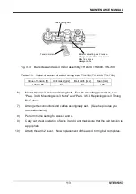
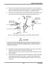
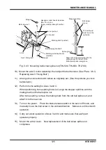
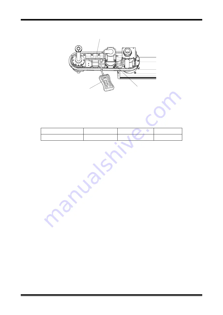
Fig. 3.33 Ball screw and axis 4 motor assembly (THL500, THL600, THL700)
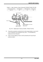
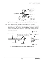
Table 3.5 Value of tension of axis 4 timing belt (THL500, THL600, THL700)
Value of tension [N]
Unit mass [g/m]
Belt width [mm]
Span [mm]
150 to 180
4.1
15
190
6)
Mount the axis 3 motor and timing belt. For the mounting procedures, see
“Para. 3.4.8, Mounting Axis 3 Motor” and “Para. 3.5.3, Replacing Axis 3 Timing
Belt” above.
7)
Arrange the connectors and cables as originally set. (See the pictures you
took beforehand.)
8)
Perform home setting for Axes 3 and 4.
9)
Carry out a test operation of Axes 3 and 4 and make sure that the belt tension is
appropriate.
10)
Attach the arm 2 cover. Now replacement of the axis 4 timing belt completes.
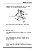
Bolts for adjusting axis 3 tension
Hexagon socket head cap screws
M4 x 16 x 2 pcs.
Hexagon nuts
Tension meter
Axis 4 timing belt

