MAINTENANCE MANUAL
34
STE 85357
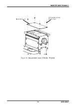
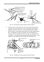
Fig. 2.13 Dismounting axis 1 wave generator (THL300, THL400)
2.4.4
Mounting Axis 1 Motor
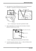
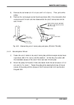
1)
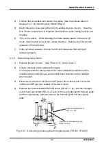
When inserting the wave generator into the axis 1 motor, be sure to fasten it
using the two jigs for fastening Axis 1. If fastened without using these jigs,
vibrations may occur when the robot is used. Install the set screws (2 pcs.) to
the wave generator. Align the holes of the set screws with the phases of the D
cuts of the axis 1 motor and insert the wave generator. Mount the fastening
jigs as shown in the figure below. While pushing down each part to make tight
contact and paying attention to the D cuts and the phases of the set screws,
tighten the set screws to fasten the wave generator. Then, pull out the
fastening jigs. In case the fastening jigs come out too easily, remount them in
such a way that some force is required to pull them out.
Fig. 2.14 Mounting axis 1 wave generator (THL300, THL400)
Set screws (2 pcs.)
Wave generator
Axis 1 motor
Wave generator
Set screws (2 pcs.)
(Apply medium strength Loctite.)
Axis 1 motor
Axis
Set screw holes
Tighten the set screws
while pushing down each
part so as not to create
gaps in between parts.
A
A
Cross section A-A
Fastening jigs
(S890900)
D cuts
(Flat plane of axis)

