


MAINTENANCE MANUAL
36
STE 85357
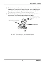
5)
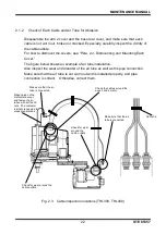
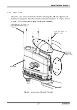
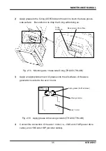
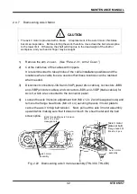
Insert the axis 1 motor assembly into the base while paying attention to the
motor's mounting phases, the orientations of the reduction gear's main body and
wave generator when the motor is inserted (align the long sides of the ovals of
the reduction gear and the wave generator), and the position of the O-ring (it
should not move). Do not forcibly push in the motor.
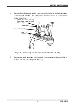
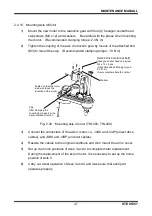
6)
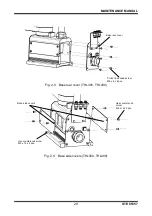
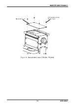
Secure the axis 1 motor assembly with four (4) hexagon socket head cap
screws (M4 x 12) and washers.
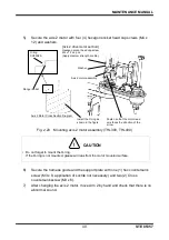
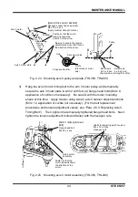
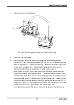
Fig. 2.17 Mounting axis 1 motor assembly (THL300, THL400)
7)
After changing Axis 1 motor, move Arm 1 by hand and check that there is no
abnormal sound before turning on the power.
8)
Mount the base front cover and the base side covers. (See
“Para. 2.3.2, Base
Covers.”)
9)
Turn on the power and set up the axis 1 home position to complete axis 1 motor
replacement.
(Check the coordinates of Axes 2 to 4 and set up the home position if necessary.
See “Section 5, Robot Home Point and Position Detector Error”.)
[Axis 1 drive motor
set bolt]
Hexagon socket head
cap screws
M4 x 12 x 4 pcs.
(Apply medium
strength Loctite.)
Axis 1 motor assembly
Washer
Fasten so that the motor
lead wire faces the
direction of the arrow.