


MAINTENANCE MANUAL
108
STE 85357
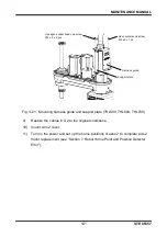
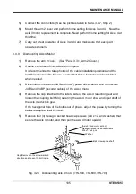
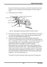
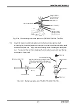
3.5.2
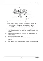
Timing Belt Locations
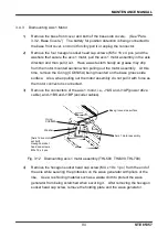
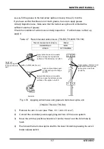
Fig. 3.28 Timing belt locations (THL500, THL600, THL700)
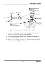
3.5.3
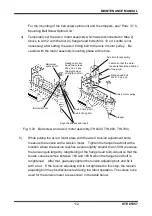
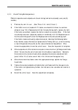
Replacing Axis 3 Timing Belt
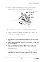
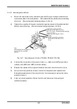
1)
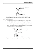
Remove t
he arm 2 cover. (See “Para. 3.3.1, Arm 2 Cover.”)
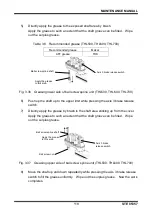
2)
Cut the cable ties of the cables with nippers. It is recommended to take photos
of the cable installation positions and the locations where cable ties are used so
that these locations can be restored when needed.
3)
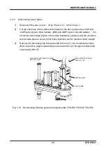
Disconnect the axis 3 motor assembly. For the disconnecting procedures, see
Steps 1) through 4) of “Para. 3.4.7, Dismounting Axis 3 Motor.”
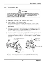
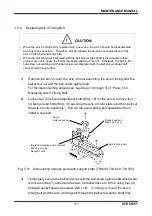
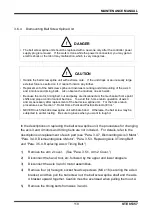
!
CAUTION
• The axis 3 motor is provided with a brake. At replacement of the axis 3 timing belt, this
brake becomes inoperative. Before starting the work, therefore, move down the shaft to
the lower limit. Otherwise, the shaft will drop due to the dead weight of the shaft or
workpiece, and your hand or finger may be caught.
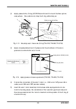
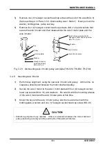
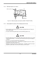
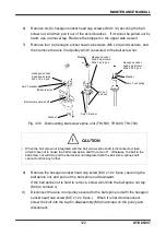
4)
Remove the four (4) hexagon socket head cap screws (M4 x 16) and the bottom
stopper that secure the axis 4 bracket (remove the hand and other parts). Pull
out the ball screw nut together with the axis 4 bracket, the ball screw shaft and
the top stopper from Arm 2. Caution must be exercised when pulling them out.
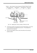
Axis 3 timing belt
Axis 4 timing belt