background image

e-STUDIO350/352/353/450/452/453

© 2003 - 2008 TOSHIBA TEC CORPORATION All rights reserved

FIRMWARE UPDATING

6 - 74

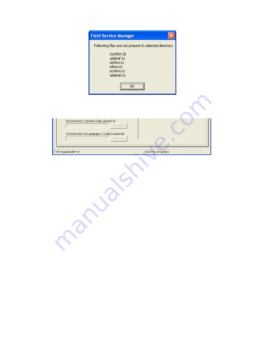
(12) The selected data is transmitted to the equipment. 

The data file name being transmitted and transmission condition are displayed at the bottom. 

Tip:

During transmission, the message “WAIT” or “NOW SERVICING” is displayed on the LCD 
screen of the equipment. In this case, all the button operations are locked. 

Содержание e-Studio 350

Страница 1: ...ERVICE HANDBOOK MULTIFUNCTIONAL DIGITAL SYSTEMS e STUDIO350 450 e STUDIO352 452 e STUDIO353 453 Model DP 3520 3540 4520 4540 Publish Date November 2003 File No SHE030005S0 R03092141302 TTEC Ver19_2008 07 ...

Страница 2: ...er countries Apple AppleTalk Macintosh and Mac are trademarks of Apple Computer Inc in the U S and other countries PostScript is a trademark of Adobe Systems Incorporated NOVELL NetWare and NDS are trademarks or registered trademarks of Novell Inc Molykote is a registered trademark of Dow Corning Corporation iCLASS is a trademark of HID Corporation MIFARE is a trademark of Royal Philips Electronic...

Страница 3: ...en trans porting the equipment Be sure to use a dedicated outlet with AC 110V 13 2A 115V or 127V 12A 220 240V or 240V 8A for its power source The equipment must be grounded for safety Never ground it to a gas pipe or a water pipe Select a suitable place for installation Avoid excessive heat high humidity dust vibration and direct sunlight Also provide proper ventilation as the equipment emits a sl...

Страница 4: ... breaker door switch fuse thermostat thermofuse thermistor batteries IC RAMs including lithium batteries etc are particularly important for safety Be sure to handle install them properly If these parts are shorted circuit and or made their functions out they may burn down for instance and may result in fatal accidents Do not allow a short circuit to occur Do not use the parts not recommended by To...

Страница 5: ...hium batteries according to this manual Attention Se débarrasser de batteries et IC RAMs usés y compris les batteries en lithium selon ce manuel Vorsicht Entsorgung der gebrauchten Batterien und IC RAMs inklusive der Lithium Batterie nach diesem Handbuch 06 09 ...

Страница 6: ......

Страница 7: ...0 450 2 82 2 2 8 Setting mode 08 e STUDIO352 353 452 453 2 144 2 2 9 Pixel counter 2 243 2 2 10 Classification List of Adjustment Mode 05 Setting Mode 08 e STUDIO350 450 2 251 2 2 11 Classification List of Adjustment Mode 05 Setting Mode 08 e STUDIO352 353 452 453 2 258 3 ADJUSTMENT 3 1 3 1 Adjustment of Auto Toner Sensor 3 1 3 2 Image Dimensional Adjustment 3 3 3 2 1 General description 3 3 3 2 2...

Страница 8: ... 3 11 4 Adjustment of the Leading Edge Position 3 78 3 11 5 Adjustment of Horizontal Position 3 79 3 11 6 Adjustment of Copy Ratio 3 81 3 11 7 Adjustment of RADF Opening Closing Sensor 3 82 3 12 Adjustment of the Finisher MJ 1022 3 83 3 12 1 Adjusting the jogging plate width 3 83 3 12 2 Adjusting the angle of the jogging plate 3 85 3 12 3 Adjusting the overlap of the sensor flag 3 86 3 12 4 Adjust...

Страница 9: ...5 1 4 Transport jam RADF 5 26 5 1 5 Finisher jam 5 32 5 1 6 Drive system related service call 5 56 5 1 7 Paper feeding system related service call 5 57 5 1 8 Scanning system related service call 5 63 5 1 9 Fuser unit related service call 5 65 5 1 10 Communication related service call 5 69 5 1 11 RADF related service call MR 3015 5 70 5 1 12 RADF related service call MR 3018 5 71 5 1 13 Laser optic...

Страница 10: ... 8 REMOTE SERVICE 8 1 8 1 Auto Supply Order 8 1 8 1 1 Outline 8 1 8 1 2 Setting Item 8 2 8 1 3 Setting procedure 8 4 8 1 4 Order Sheet Format 8 11 8 2 Service Notification 8 13 8 2 1 Outline 8 13 8 2 2 Setting e STUDIO350 450 8 13 8 2 3 Items to be notified e STUDIO350 450 8 18 8 2 4 Setting e STUDIO352 353 452 453 8 23 8 2 5 Items to be notified e STUDIO352 353 452 453 8 29 9 DATA CLONING with US...

Страница 11: ...le side multiple copying When the RADF is used the copy speed of 35 45 sheets per minute is only available under the fol lowing conditions Original Mode Single side original A4 LT size APS automatic density are not selected Number of sheets 35 45 or more Paper feeding LCF Reproduction ratio 100 Values in are for e STUDIO450 452 453 in case that the specification is different between e STUDIO350 35...

Страница 12: ...5 to 200 when using RADF y Resolution Gradation Scanning 600 dpi x 600 dpi Printing Equivalent to 2400 dpi x 600 dpi Gradation 256 steps y Eliminated portion Leading edges 3 0 2 0 mm Side trailing edges 2 0 2 0 mm copy Leading trailing edges 5 0 2 0 mm Side edges 5 0 2 0 mm print Copy mode Sec e STUDIO350 352 353 e STUDIO450 452 453 Single sided originals Single sided copies 1 set 20 85 17 49 3 se...

Страница 13: ... 80 g m2 Stack height 16 mm or less y Automatic duplexing unit Stackless Switchback type y Toner supply Automatic toner density detection supply Toner cartridge replacing method y Density control Automatic density mode and manual density mode selectable in 11 steps y Weight 83 kg 183 lb e STUDIO350 450 86 kg 189 59 lb e STUDIO352 353 452 453 y Power requirements AC 110 V 10 13 2 A 115 V 10 or 127 ...

Страница 14: ...China ASU Asia KRD Korea Unpacking Setup instruction 1 set Operator s manual 4 pcs except for MJD Operator s manual pocket 1 pc Power cable 1 pc Warranty sheet 1 pc for NAD Setup report 1 set for NAD and MJD PM sticker 1 pc for MJD Drum installed inside of the equipment 1 pc for MJD Toner bag 1 pc Toner cartridge 1 pc except for NAD and MJD Developer material 1 pc except for NAD and MJD Operation ...

Страница 15: ...eeder RADF MR 3015 Drawer module MY 1021 C Paper Feed Pedestal PFP KD 1011 C Large Capacity Feeder LCF KD 1012 A4 LT A4 C Finisher Hanging type MJ 1022 C Finisher Console type MJ 1023 C Finisher Console saddle stitcher type MJ 1024 C Hole punch unit MJ 6004 N E F S 1 Staple cartridge STAPLE 1600 for MJ 1022 STAPLE 2000 for MJ 1023 1024 STAPLE 600 for MJ 1024 Bridge kit KN 3520 C Job Separator MJ 5...

Страница 16: ...1024 MJ 6004 N E F S Staple cartridge STAPLE 1600 for MJ 1022 STAPLE 2400 for MJ 1101 STAPLE 2000 for MJ 1023 1024 STAPLE 600 for saddle stitcher of MJ 1024 Bridge kit KN 3520 C Job Separator MJ 5004 C Offset Tray MJ 5005 C Work Tray KK 3511 Damp Heater MF 3520 U E Fax Board GD 1200 NA EU AU AS C TW KR 2nd Line for Fax Board GD 1160 NA EU N C TW Printer Kit GM 1060 1061 Printer Scanner Kit GM 2060...

Страница 17: ...tallation of the scrambler board GP 1040 4 The antenna GN 3010 is necessary to enable the wireless LAN module GN 1041 and Bluetooth module GN 2010 5 When the wireless LAN module GN 1041 and the Bluetooth module GN 2010 are installed only 1 antenna GN 3010 can be connected to each 6 The Printer kit GM 1060 or Printer Scanner kit GM 2060 does not have a function for print ing an XPS file 7 To enable...

Страница 18: ... ACCESSORIES OPTIONS SUPPLIES 1 8 1 4 Supplies 2 N Asia E Europe NONE North America 3 T Taiwan D Asia C China E Europe NONE North America Drum OD 3500 Toner bag PS TB3520 E N 2 Toner cartridge PS ZT3520 T D C E 3 e STUDIO350 352 450 452 PS ZT3520C 3 PS ZT4520 E 3 e STUDIO353 453 Developer D 3500 07 11 ...

Страница 19: ...5005 Scrambler Board GP 1030 PCI Slot GO 1030 FAX Board GD 1150 NA AU EU TW C AS 2nd Line for FAX Board GD 1160 NA EU TW C Wireless LAN Adapter GN 1010 Damp Heater MF 3520 U E Data overwrite kit GP 1050 Printer Kit GM 1010 Desk MH 1700 Drawer Module MY 1021 Large Capacity Feeder LCF KD 1012 A4 LT Paper Feed Pedestal PFP KD 1011 Printer Scanner Kit GM 2010 Scanner Upgrade Kit GM 3010 Staple Cartrid...

Страница 20: ...1 Reversing Automatic Document Feeder RADF MR 3018 Bridge Kit KN 3520 Job Separator MJ 5004 Offset Tray MJ 5005 Scrambler Board GP 1040 PCI Slot GO 1060 FAX Board GD 1200 NA EU AU AS C TW KR 2nd Line for FAX Board GD 1160 NA EU N TW C Damp Heater MF 3520 U E Desk MH 1700 Drawer Module MY 1021 Large Capacity Feeder LCF KD 1012 A4 LT Paper Feed Pedestal PFP KD 1011 Hole Punch Unit MJ 6101 N E F S St...

Страница 21: ...rect paper size setting for PFP upper drawer The size of paper in the 3rd drawer differs from size setting of the equipment P 5 2 E064 Incorrect paper size setting for PFP lower drawer The size of paper in the 4th drawer differs from size setting of the equipment P 5 2 E065 Incorrect paper size setting for bypass tray The size of paper in the bypass tray differs from size setting of the equipment ...

Страница 22: ...paper does not reach the upper drawer feed sensor after it has passed the lower drawer feed sensor P 5 4 E320 PFP upper drawer transport jam Paper not reach ing the lower drawer feed sensor The paper does not reach the lower drawer feed sensor after it has passed the PFP upper drawer feed sensor P 5 5 E330 PFP lower drawer transport jam Paper not reach ing the registration sensor The paper does no...

Страница 23: ...r after it is switchbacked in the exit section P 5 8 E550 Other paper jam Paper remaining jam on the transport path The paper is remaining on the transport path when print ing is finished caused by a multiple paper feeding P 5 9 E711 RADF jam Jam not reaching the original length sensor The original fed from the original feeding tray does not reach the original length sensor P 5 26 E712 Jam not rea...

Страница 24: ... cover has opened during RADF operation P 5 30 E870 RADF open jam RADF has opened during RADF operation P 5 31 E910 Finisher jam Bridge unit Jam at the bridge unit transport sensor 1 The paper does not reach the bridge unit transport sen sor 1 after it has passed the exit sensor P 5 32 E920 Stop jam at the bridge unit transport sensor 1 The trailing edge of the paper does not pass the bridge unit ...

Страница 25: ... passed through the inlet sensor does not reach the transport sensor MJ 1101 P 5 38 EA32 Exit paper remaining jam The paper is remaining on the finishing tray when the power is turned ON MJ 1101 P 5 38 EA40 Door open jam 1 The finisher has been released from the equip ment during printing MJ 1022 2 The upper front cover of the finisher unit or the upper front door of the puncher unit has opened du...

Страница 26: ... is disabled because of the communication error between the equipment and finisher at the start of printing P 5 51 EB50 Paper transport jam Paper remaining on the transport path The multiple feeding of preceding paper caused the misfeeding of upcoming paper P 5 11 EB60 Paper remaining on the transport path The multiple feeding of preceding paper caused the misfeeding of upcoming paper redetection ...

Страница 27: ...drawer P 5 59 C180 LCF tray motor abnormality The LCF tray motor is not rotating or the LCF tray is not moving normally the case that paper can be fed from any drawer except the LCF P 5 60 C1A0 LCF end fence motor abnormality The LCF end fence motor is not rotating or the LCF end fence is not moving normally the case that paper can be fed from any drawer except the LCF P 5 61 C1B0 LCF transport mo...

Страница 28: ...otor is not rotat ing normally P 5 70 C820 Read sensor adjustment error The read sensor cannot be adjusted normally when performing the code 05 356 P 5 70 C830 Original length sensor adjustment error The origi nal length sensor cannot be adjusted normally when performing the code 05 356 P 5 70 C940 Circuit related service call Engine CPU abnormality P 5 91 C970 Process related ser vice call High v...

Страница 29: ...it shift motor abnormality The stapler unit shift motor is not rotating or the stapler is not mov ing normally MJ 1023 1024 1101 P 5 76 CB80 Backup RAM data abnormality 1 Abnormality of checksum value on finisher con troller board is detected when the power is turned on MJ 1023 1024 2 Abnormality of checksum value on punch driver board is detected when the power is turned on MJ 1023 1024 when MJ 6...

Страница 30: ...1 P 5 81 CC40 Swing motor abnormality Swing motor is not rotat ing or swing unit is not moving normally MJ 1023 1024 P 5 81 CC41 Paper holder cam home position abnormality The paper holder cam is not at the home position MJ 1101 P 5 82 CC50 Horizontal registration motor abnormality Horizon tal registration motor is not rotating or puncher is not shifting normally MJ 1023 1024 when MJ 6004 is insta...

Страница 31: ...ing or the paddle is not rotating normally MJ 1101 P 5 89 CDF0 Offset tray related ser vice call Initialization error of the offset tray The home posi tion of the separator cannot be detected when the power is turned ON P 5 91 CE00 Finisher related ser vice call Communication error between finisher unit and puncher unit Communication error between fin isher controller PC board and punch controller...

Страница 32: ... partition damage P 5 93 F107 SHR partition damage P 5 93 F108 SHA partition damage P 5 93 F110 Communication related service call Communication error between System CPU and Scanner CPU P 5 69 F111 Other service call Scanner response abnormality P 5 69 F120 Database abnormality Database is not operating normally P 5 93 F130 Invalid MAC address P 5 93 F200 Data overwrite Kit GP 1050 1060 is taken o...

Страница 33: ... 5 95 1C32 File deletion failure P 5 94 1C33 File access failure P 5 95 1C40 Image conversion abnormality P 5 95 1C60 HDD full failure during processing P 5 95 1C61 Address Book reading failure P 5 95 1C62 Memory acquiring failure P 5 95 1C63 Terminal IP address unset P 5 95 1C64 Terminal mail address unset P 5 95 1C65 SMTP address unset P 5 95 1C66 Server time time out error P 5 95 1C67 NIC time ...

Страница 34: ...l mail address error RFC 500 P 5 97 2501 Syntax error in parameters or argu ments HOST NAME error RFC 501 Destination mail address error RFC 501 Terminal mail address error RFC 501 P 5 97 2503 Bad sequence of commands Destination mail address error RFC 503 P 5 97 2504 Command parameter not imple mented HOST NAME error RFC 504 P 5 97 2550 Mailbox unavailable Destination mail address error RFC 550 P...

Страница 35: ...lder with the same name exists in the box 2B70 The document was renamed A doc ument of the same name already existed A document with the same name exists in the box or folder 2B71 Document s expire s in a few days Documents expiring in a few days exist 2B80 Hard Disk space for Electronic Filing nearly full Hard disk space in SHR partition is nearly full 90 2B90 Insufficient Memory Insufficient mem...

Страница 36: ...was not per mitted Encryption PDF enforced mode error P 5 101 2C60 Failed to process your Job Insuffi cient disk space HDD full failure during processing P 5 101 2C61 Failed to read AddressBook Address Book reading failure P 5 101 2C62 Not enough memory Memory acquiring failure P 5 100 2C63 Invalid Domain Address Terminal IP address unset P 5 101 2C64 Invalid Domain Address Terminal mail address u...

Страница 37: ...iled to connect to network destina tion Check destination path File server connection error P 5 104 2D63 Specified network path is invalid Check destination path Invalid network path P 5 104 2D64 Logon to file server failed Check user name and password Login failure P 5 104 2D65 There are too many documents in the folder Failed in creating new document Exceeding documents in folder Creating new do...

Страница 38: ...artial Mail Error has been detected in the received mail Partial mail related error P 5 105 3A50 HDD Full Error has been occurred in this mail Insufficient HDD capacity error P 5 105 3A51 HDD Full Error has been occurred in this mail This mail has been trans ferred to the administrator P 5 105 3A52 HDD Full Error has been occurred in this mail This mail could not be transferred to the administrato...

Страница 39: ...ved mail This mail could not be transferred to the administrator P 5 105 3B40 Decode Error has been detected in the received mail E mail decode error P 5 105 3B41 Decode Error has been detected in the received mail This mail has been transferred to the administrator P 5 105 3B42 Decode Error has been detected in the received mail This mail could not be transferred to the administrator P 5 105 3C10...

Страница 40: ...eceived mail This mail could not be transferred to the administrator P 5 106 3C60 Offramp Security Error has been detected in the received mail Offramp security error P 5 106 3C61 Offramp Security Error has been detected in the received mail This mail has been transferred to the administrator P 5 106 3C62 Offramp Security Error has been detected in the received mail This mail could not be transfer...

Страница 41: ...DE AND SELF DIAGNOSTIC MODE 2 21 2 3F00 File I O Error has been occurred in this mail The mail could not be received until File I O is recovered File I O error P 5 107 3F10 P 5 107 3F20 P 5 107 3F30 P 5 107 3F40 P 5 107 Error code Message displayed in the TopAccess screen Contents Troubleshooting ...

Страница 42: ...ata being stored to the HDD temporarily Proof print Private print Scheduled print etc cannot be performed P 5 107 4034 e Filing storing limitation error Printing with its data being stored to the HDD print and e Filing print to e Filing etc cannot be performed P 5 107 4035 Local file storing limitation error Network FAX or Internet FAX cannot be sent when Local is selected for the destination of t...

Страница 43: ...ed L Unused M 8K N 16K R O 16K Z Not selected C Sort mode staple mode 0 Non sort Non staple 1 Group 2 Sort 7 Front staple8 Double staple 9 Rear staple A Saddle stitch D ADF mode 0 Unused 1 AUTO FEED SADF 2 STACK FEED E APS AMS mode 0 Not selected 1 APS 2 AMS F Duplex mode 0 Not selected 1 Book 2 Double sided Single sided 4 Double sided Duplex copying 8 Single sided Duplex copying G Unused H Image ...

Страница 44: ... card J 8 5SQK Unused L Unused M 8K N 16K R O 16K Z Not selected C Sort mode staple mode 0 Non sort Non staple 1 Group 2 Sort 7 Front staple8 Double staple 9 Rear staple A Saddle stitch D ADF mode 0 Unused 1 AUTO FEED SADF 2 STACK FEED E APS AMS mode 0 Not selected 1 APS 2 AMS F Duplex mode 0 Not selected 1 Book 2 Double sided Single sided 4 Double sided Duplex copying 8 Single sided Duplex copyin...

Страница 45: ...r to P 2 27 2 2 1 Input check Test mode 03 e STUDIO350 450 P 2 34 2 2 2 Input check Test mode 03 e STUDIO352 353 452 453 and P 2 42 2 2 3 Output check test mode 03 Test print mode 04 Refer to P 2 45 2 2 4 Test print mode test mode 04 Adjustment mode 05 Refer to P 2 46 2 2 5 Adjustment mode 05 e STUDIO350 450 P 2 64 2 2 6 Adjustment mode 05 e STUDIO352 353 452 453 Mode For start Contents For exit D...

Страница 46: ...tting mode 08 Code 103 PM support mode 104 Stored information of pixel counter toner cartridge reference 105 Stored information of pixel counter service technician reference 106 Error history Digital keys Key in the first code to be printed Digital keys Key in the last code to be printed POWER OFF ON Exit START List starts to be printed START START 6 START POWER Code 1 Auto toner adjustment 2 PM S...

Страница 47: ...est mode Fig 2 2 Example of display during input check Items to be checked and the condition of the equipment when the buttons A to H are highlighted are listed in the following pages The status of each input signal can be checked by pressing the FAX button and the digital keys in the test mode 03 0 3 POWER START FAX Digital keys CLEAR LCD ON POWER OFF ON Exit 0 5 POWER POWER OFF ON Exit Digital k...

Страница 48: ...d Connected F PFP side cover opening closing switch Cover opened Cover closed G PFP upper drawer empty sensor No paper Paper present H PFP upper drawer tray up sensor Tray at upper limit position Other than upper limit position 3 A LCF tray bottom sensor Tray at bottom position Other than bottom posi tion B LCF standby side paper mis stacking sensor Correct stack ing Incorrect stacking C D E LCF d...

Страница 49: ...er drawer tray up sensor Tray at upper limit position Other than upper limit position 7 A B C D E Lower drawer feed sensor Paper present No paper F G Lower drawer empty sensor No paper Paper present H Lower drawer tray up sensor Tray at upper limit position Other than upper limit position 8 A B Bypass feed paper width sensor 3 Refer to table 1 C Bypass feed paper width sensor 2 Refer to table 1 D ...

Страница 50: ... Drawer present E Upper drawer paper stock sensor Paper almost empty Paper present F G H 0 A B C D Lower drawer detection switch Drawer not installed Drawer present E Lower drawer paper stock sensor Paper almost empty Paper present F G H Bypass paper width sensor Paper width size 3 2 1 0 0 1 1 1 A3 LD 1 0 1 1 A4 R LT R 1 1 0 1 A5 R ST R 1 1 1 0 Card size 0 0 1 1 B4 R LG 1 0 0 1 B5 R Digital key Bu...

Страница 51: ...s Motor is rotating at Output Mode 03 Abnormal rota tion Normal rota tion 3 A B Key copy counter connection Not connected Connected C Toner bag full detection sensor 2 Toner bag full Toner bag not full D Fuser unit connection Fuser unit installed Fuser unit not installed E Bridge unit transport sensor 2 When bridge unit is installed No paper Paper present F G Bridge unit paper full detection senso...

Страница 52: ...l present 7 A RADF tray sensor Original present No original B RADF empty sensor Original present No original C RADF jam access cover switch Cover opened Cover closed D RADF opening closing sensor RADF opened RADF closed E RADF exit sensor Original present No original F RADF reverse sensor Original present No original G RADF read sensor Original present No original H RADF registration sensor Origin...

Страница 53: ...e Not connect able B Dongle for Printer kit GM 1010 Connectable Not connect able C Dongle for Scanner upgrade kit GM 3010 Connectable Not connect able D Dongles for other equipments Other USB devices Connectable Not connect able E F G H Bridge unit Job Separator Offset Tray Bridge unit Job Sepa rator Offset Tray con nection detection 1 Normal display Highlighting display Highlighting display Bridg...

Страница 54: ... test mode Fig 2 3 Example of display during input check Items to be checked and the condition of the equipment when the buttons A to H are highlighted are listed in the following pages The status of each input signal can be checked by pressing the FAX button and the digital keys in the test mode 03 0 3 POWER START FAX Digital keys CLEAR LCD ON POWER OFF ON Exit 0 5 POWER POWER OFF ON Exit Digital...

Страница 55: ...ion Not connected Connected F PFP side cover opening closing switch Cover opened Cover closed G PFP upper drawer empty sensor No paper Paper present H PFP upper drawer tray up sensor Tray at upper limit position Other than upper limit position 3 A LCF tray bottom sensor Tray at bottom position Other than bottom posi tion B LCF standby side paper mis stacking sensor Correct stack ing Incorrect stac...

Страница 56: ...r drawer tray up sensor Tray at upper limit position Other than upper limit position 7 A B C D E Lower drawer feed sensor Paper present No paper F G Lower drawer empty sensor No paper Paper present H Lower drawer tray up sensor Tray at upper limit position Other than upper limit position 8 A B Bypass feed paper width sensor 3 Refer to table 1 C Bypass feed paper width sensor 2 Refer to table 1 D B...

Страница 57: ...ed Drawer present E Upper drawer paper stock sensor Paper almost empty Paper present F G H 0 A B C D Lower drawer detection switch Drawer not installed Drawer present E Lower drawer paper stock sensor Paper almost empty Paper present F G H Bypass paper width sensor Paper width size 3 2 1 0 0 1 1 1 A3 LD 1 0 1 1 A4 R LT R 1 1 0 1 A5 R ST R 1 1 1 0 Card size 0 0 1 1 B4 R LG 1 0 0 1 B5 R Digital key ...

Страница 58: ...otation status Motor is rotating at Output Mode 03 Abnormal rota tion Normal rota tion 3 A B Key copy counter connection Not connected Connected C Toner bag full detection sensor 2 Toner bag full Toner bag not full D Fuser unit connection Fuser unit installed Fuser unit not installed E Bridge unit transport sensor 2 When bridge unit is installed No paper Paper present F G Bridge unit paper full de...

Страница 59: ...iginal C RADF Jam access cover sensor Cover opened Cover closed D RADF RADF opening closing sensor RADF opened RADF closed E RADF Original exit reverse sensor Original present No original F RADF Original intermediate transport sensor Original present No original G RADF Read sensor Original present No original H RADF Original registration sensor Original present No original 8 A RADF Original tray w...

Страница 60: ...3 Refer to table 2 D E F G H 0 A B C D E F G H Bridge unit Job Separator Offset Tray Bridge unit Job Sepa rator Offset Tray con nection detection 1 Normal display Highlighting display Highlighting display Bridge unit Job Sepa rator Offset Tray con nection detection 2 Highlighting display Highlighting display Normal display Bridge unit Job Sepa rator Offset Tray con nection detection 3 Normal displ...

Страница 61: ...re performing the check otherwise this code cannot be used It may take some time 2 sec to 10 sec before this check is completed depending on the USB storage device Digital key Button Items to check Contents Highlighted display e g Normal dis play e g 0 A Dongle for Printer Scanner kit GM 2060 Connected Connectable Not connect able B Dongle for Printer kit GM 1060 Connected Connectable Not connect ...

Страница 62: ...09 function OFF 1 110 ADU motor ON 160 Code No 110 function OFF 1 118 Laser ON 168 Code No 118 function OFF 1 120 Exit motor ON normal rotation 170 Code No 120 function OFF 1 121 Exit motor ON reverse rotation 171 Code No 121 function OFF 1 122 LCF motor ON 172 Code No 122 function OFF 1 177 Offset Tray motor ON reciprocating movement 2 201 Upper drawer feed clutch ON OFF 3 202 Lower drawer feed c...

Страница 63: ...eloper bias DC ON OFF 3 252 Main charger ON OFF 3 253 Separation bias ON OFF 3 255 Transfer guide bias ON OFF 3 256 Transfer transformer ON OFF 3 261 Scan motor ON Automatically stops at limit position speed can be changed with the ZOOM button 2 264 SLG board cooling fan 1 ON OFF 3 265 SLG board cooling fan 2 ON OFF 3 267 Scanner exposure lamp ON OFF 3 268 Laser unit cooling fan ON OFF high speed ...

Страница 64: ... 3018 3 295 Power OFF mode for 200 V series 4 297 RADF fan motor ON OFF 3 410 Power supply cooling fan ON OFF low speed 3 411 Power supply cooling fan ON OFF high speed 3 412 Middle fan ON OFF high speed 3 413 Middle fan ON OFF low speed 3 432 Developer drive clutch ON OFF 3 461 Fuser unit cooling fan ON OFF low speed 3 462 Fuser unit cooling fan ON OFF high speed 3 463 Developer unit cooling fan ...

Страница 65: ...k ON to clear the error 2 During test printing the CLEAR button is disabled when Wait adding toner is displayed The embedded test pattern can be printed out by keying in the following codes in the test print mode 04 Code Types of test pattern Remarks 111 Primary scanning direction 33 gradation steps Error diffusion 113 Secondary scanning direction 33 gradation steps Error diffusion 142 Grid patter...

Страница 66: ... mode 0 5 POWER POWER OFF ON Exit Digital key Code START CANCEL Digital key FUNCTION CLEAR Key in a value CLEAR Corrects value ENTER or INTERRUPT Stores value in RAM FAX Test copy 0 5 POWER POWER OFF ON Exit Code START ENTER or INTERRUPT Value unchangeable FAX Test copy Value displayed 0 5 POWER POWER OFF ON Exit Digital key Code START CANCEL UP or DOWN Adjust a value CLEAR Corrects value ENTER or...

Страница 67: ... and then start up the adjustment mode again Test print pattern in Adjustment Mode 05 Operation One test print is printed out when the FAX button is pressed after the code is keyed in at Standby Screen Code Types of test pattern Remarks 1 Grid pattern Refer to P 3 7 3 2 3 Printer related adjustment 3 Grid pattern Duplex printing Refer to P 3 7 3 2 3 Printer related adjustment 0 5 POWER POWER OFF O...

Страница 68: ...er unit is not installed 3 205 Devel oper Developer bias DC output adjustment ALL 189 0 255 M As the value increases the transformer output increases correspond ingly Remove the developer unit and install the adjustment jig to make adjust ment However the adjustment jig is not necessary to adjust the developer bias DC P 3 29 3 210 Charger Main charger grid bias out put adjustment ALL 154 0 255 M 3...

Страница 69: ...stment of RADF transport speed ALL 50 0 100 SYS When the value increases by 1 the reproduction ratio of the secondary scan ning direction when using the RADF increases by approx 0 1 1 358 RADF RADF sideways deviation adjustment ALL 128 0 255 SYS When the value increases by 1 the image of original fed from the RADF shifts toward the rear side of paper by approx 0 0846mm 1 359 Scanner Carriage posit...

Страница 70: ...ases by approx 0 07 approx 0 1mm step 1 405 PPC 129 0 255 M 410 Laser Adjustment of primary scanning laser writing start position PPC 128 0 255 M When the value increases by 1 the writing start position shifts to the front side by approx 0 0423mm 1 411 PRT 128 0 255 M 421 Drive Adjustment of secondary scanning direction repro duction ratio fine adjust ment of main motor speed PPC PRT 138 0 255 M W...

Страница 71: ...PC PRT 12 0 255 M 4 435 Image Top margin adjustment blank area at the leading edge of the paper PRT 24 0 255 M 1 436 Image Left margin adjustment blank area at the left of the paper along the paper feeding direction PRT 0 0 255 M 1 437 Image Right margin adjustment blank area at the right of the paper along the paper feeding direction PRT 0 0 255 M 1 438 Image Bottom margin adjustment blank area a...

Страница 72: ...63 M 4 449 2 Short size ALL 8 0 63 M 4 450 0 Paper feeding Paperaligning amount adjustment at the registra tion section Upperdrawer Plain paper Long size ALL 17 0 63 M 4 450 1 Middle size ALL 17 0 63 M 4 450 2 Short size ALL 17 0 63 M 4 452 0 Paper feeding Paperaligning amount adjustment at the registra tion section Lowerdrawer Plain paper Long size ALL 12 0 63 M 4 452 1 Middle size ALL 10 0 63 M ...

Страница 73: ...e size ALL 17 0 63 M 4 461 2 Short size ALL 17 0 63 M 4 462 0 Paper feeding Paperaligning amount adjustment at the registra tion section Bypass feed ing Thick paper 3 Long size ALL 17 0 63 M 4 462 1 Middle size ALL 17 0 63 M 4 462 2 Short size ALL 17 0 63 M 4 462 3 Post card ALL 14 0 63 M 4 463 0 Paper feeding Paperaligning amount adjustment at the registra tion section Bypass feed ing OHP film Lo...

Страница 74: ...ze ALL 20 0 63 M When the value increases by 1 the aligning amount increases by approx 0 8 mm Paper length Long size 330 mm or longer Middle size 220 mm to 329 mm Short size 219 mm or shorter 4 469 1 Thick Paper 1 Middle size ALL 20 0 63 M 4 469 2 Thick Paper 1 Short size ALL 20 0 63 M 4 469 3 Thick Paper 2 Long size ALL 20 0 63 M 4 469 4 Thick Paper 2 Middle size ALL 22 0 63 M 4 469 5 Thick Paper...

Страница 75: ... value increases by 1 the image shifts toward the front side by 0 0423 mm 4 497 1 Lower drawer ALL 128 0 255 M 4 497 2 PFPupper drawer ALL 128 0 255 M 4 497 3 PFP lower drawer ALL 128 0 255 M 4 497 4 LCF ALL 128 0 255 M 4 497 5 Bypass feeding ALL 128 0 255 M 4 498 0 Laser Adjustment of primary scan ning laser writing start position at duplex feed ing Long size ALL 148 0 255 M When the value increa...

Страница 76: ...increases the back ground becomes more brightened 1 533 Photo PPC 16 0 255 SYS 1 534 Text PPC 64 0 255 SYS 1 570 Image Range correc tion on origi nal manually set on the original glass Text Photo PPC EUR 12 UC 12 JPN 22 11 14 21 24 31 34 41 44 SYS Sets whether the val ues of the background peak and text peak are fixed or not One s place is an adjustment for automatic density and ten s place is for...

Страница 77: ...alue decreases the image becomes softer The smaller the value is the less the moire becomes One s place Fixed value 05 620 is 1 05 621 is 2 05 622 is 5 Ten s place Sharpness intensity 0 Use default value 1 9 Filter intensity 1 621 Photo PPC 2 0 99 SYS 1 622 Text PPC EUR 45 UC 45 JPN 45 0 99 SYS 1 653 Image Adjustment of smudged faint text Text Photo PPC 208 0 255 SYS Adjusts the level of the smudg...

Страница 78: ...utomatic density and ten s place is for manual density Once they are fixed the range correction is per formed with standard values The values of the back ground peak and text peak affect the repro duction of the back ground density and text density respectively 1 fixed fixed 2 varied fixed 3 fixed varied 4 varied varied Background peak Text peak 1 694 Photo PPC 12 11 14 21 24 31 34 41 44 SYS 1 695...

Страница 79: ...Density adjustment Fine adjust ment of auto matic density Photo FAX 128 0 255 SYS When the value increases the image becomes darker 1 729 Text Photo FAX 128 0 255 SYS 1 825 Image Range correc tion on origi nal manually set on the original glass Text Photo SCN 12 11 14 21 24 31 34 41 44 SYS Sets whether the val ues of the background peak and text peak are fixed or not One s place is an adjustment f...

Страница 80: ... brightened 1 836 Text SCN 48 0 255 SYS 1 837 Photo SCN 40 0 255 SYS 1 845 Image Density adjustment Fine adjust ment of man ual density Center value Text Photo SCN 128 0 255 SYS When the value increases the image at the center step becomes darker 1 846 Text SCN 128 0 255 SYS 1 847 Photo SCN 128 0 255 SYS 1 850 Image Density adjustment Fine adjust ment of man ual density Light step value Text Photo...

Страница 81: ...pnessad just ment Photo Reproduc tion ratio 40 or smaller SCN 5 0 99 SYS 4 867 1 Reproduc tion ratio 41 80 SCN 5 0 99 SYS 4 867 2 Reproduc tion ratio 81 or larger SCN 5 0 99 SYS 4 913 Image Range correc tion on origi nal manually set on the original glass Custom Mode 1 PPC EUR 12 UC 12 JPN 22 11 14 21 24 31 34 41 44 SYS Set whether the values of the background peak and text peak are fixed or not O...

Страница 82: ...919 Image Range correc tion Back ground peak adjustment Custom Mode 1 PPC 40 0 255 SYS When the value increases the back ground becomes more brightened 1 920 Image Custom Mode 2 PPC 64 0 255 SYS 1 921 Image Custom Mode 3 PPC 16 0 255 SYS 1 922 Image Sharpness adjustment Custom Mode 1 PPC 1 0 99 SYS When the value increases the image becomes sharper When the value decreases the image becomes softer...

Страница 83: ...r 1 938 Custom Mode 2 PPC 20 0 255 SYS 1 939 Custom Mode 3 PPC 20 0 255 SYS 1 940 Image Density adjustment Fine adjust ment of auto matic density Custom Mode 1 PPC 128 0 255 SYS When the value increases the image becomes darker 1 941 Custom Mode 2 PPC 128 0 255 SYS 1 942 Custom Mode 3 PPC 128 0 255 SYS 1 943 Image Gamma data slope adjust ment Custom Mode 1 PPC 0 0 99 SYS One s place 0 Equivalent t...

Страница 84: ...this mode 0 5 POWER POWER OFF ON Exit Digital key Code START CANCEL Digital key FUNCTION CLEAR Key in a value CLEAR Corrects value ENTER or INTERRUPT Stores value in RAM FAX Test copy 0 5 POWER POWER OFF ON Exit Code START ENTER or INTERRUPT Value unchangeable FAX Test copy Value displayed 0 5 POWER POWER OFF ON Exit Digital key Code START CANCEL UP or DOWN Adjust a value CLEAR Corrects value ENTE...

Страница 85: ... and then start up the adjustment mode again Test print pattern in Adjustment Mode 05 Operation One test print is printed out when the FAX button is pressed after the code is keyed in at Standby Screen Code Types of test pattern Remarks 1 Grid pattern Refer to P 3 7 3 2 3 Printer related adjustment 3 Grid pattern Duplex printing Refer to P 3 7 3 2 3 Printer related adjustment 0 5 POWER POWER OFF O...

Страница 86: ...eloper unit is not installed 3 205 Devel oper Developer bias DC output adjustment ALL 189 0 255 M As the value increases the transformer output increases correspond ingly Remove the developer unit and install the adjustment jig to make adjust ment However the adjustment jig is not necessary to adjust the developer bias DC P 3 29 3 210 Charger Main charger grid bias out put adjustment ALL 154 0 255...

Страница 87: ...approx 0 1 1 358 RADF RADF sideways deviation adjustment ALL 128 0 255 SYS When the value increases by 1 the image of original fed from the RADF shifts toward the rear side of paper by approx 0 0846mm 1 359 Scanner Carriage position adjust ment during scanning from RADF ALL 128 0 255 SYS When the value increases by 1 the carriage position when using the RADF shifts by approx 0 1 mm toward the orig...

Страница 88: ...aper feeding direction PPC 0 0 255 M 1 432 Image Right margin adjustment blank area at the right of the paper along the paper feeding direction PPC 0 0 255 M When the value increases by 1 the blank area becomes wider by approx 0 0423 mm 1 433 Image Bottom margin adjustment blank area at the trailing edge of the paper PPC 0 0 255 M 1 434 0 Image Bottom margin adjustment blank area at the trailing e...

Страница 89: ... M 4 449 0 Paper feeding Paperaligning amount adjustment at the registra tion section PFP lower drawer Plain paper Long size ALL 10 0 63 M 4 449 1 Middle size ALL 10 0 63 M 4 449 2 Short size ALL 8 0 63 M 4 450 0 Paper feeding Paperaligning amount adjustment at the registra tion section Upperdrawer Plain paper Long size ALL 17 0 63 M 4 450 1 Middle size ALL 17 0 63 M 4 450 2 Short size ALL 17 0 63...

Страница 90: ...L 17 0 63 M 4 461 2 Short size ALL 17 0 63 M 4 462 0 Paper feeding Paperaligning amount adjustment at the registra tion section Bypass feed ing Thick paper 3 Long size ALL 17 0 63 M 4 462 1 Middle size ALL 17 0 63 M 4 462 2 Short size ALL 17 0 63 M 4 462 3 Post card ALL 14 0 63 M 4 463 0 Paper feeding Paperaligning amount adjustment at the registra tion section Bypass feed ing OHP film Long size A...

Страница 91: ... 20 0 63 M When the value increases by 1 the aligning amount increases by approx 0 8 mm Paper length Long size 330 mm or longer Middle size 220 mm to 329 mm Short size 219 mm or shorter 4 469 1 Thick Paper 1 Middle size ALL 20 0 63 M 4 469 2 Thick Paper 1 Short size ALL 20 0 63 M 4 469 3 Thick Paper 2 Long size ALL 20 0 63 M 4 469 4 Thick Paper 2 Middle size ALL 22 0 63 M 4 469 5 Thick Paper 2 Sho...

Страница 92: ...e increases by 1 the image shifts toward the front side by 0 0423 mm 4 497 1 Lower drawer ALL 128 0 255 M 4 497 2 PFPupper drawer ALL 128 0 255 M 4 497 3 PFP lower drawer ALL 128 0 255 M 4 497 4 LCF ALL 128 0 255 M 4 497 5 Bypass feeding ALL 128 0 255 M 4 498 0 Laser Adjustment of primary scan ning laser writing start position at duplex feed ing Long size ALL 148 0 255 M When the value increases b...

Страница 93: ...creases the back ground becomes more brightened 1 533 Photo PPC 16 0 255 SYS 1 534 Text PPC 64 0 255 SYS 1 570 Image Range correc tion on origi nal manually set on the original glass Text Photo PPC EUR 12 UC 12 JPN 22 11 14 21 24 31 34 41 44 SYS Sets whether the val ues of the background peak and text peak are fixed or not One s place is an adjustment for automatic density and ten s place is for m...

Страница 94: ...higher 4 597 1 Image Medium density PRT 128 0 255 SYS 4 597 2 Image High density PRT 128 0 255 SYS 4 598 0 Image Gamma bal ance adjust ment PCL Photo Low density PRT 128 0 255 SYS When the value increases the density in the target area becomes higher 4 598 1 Image Medium density PRT 128 0 255 SYS 4 598 2 Image High density PRT 128 0 255 SYS 4 599 0 Image Adjustment of gamma bal ance PCL Detail Low...

Страница 95: ...faint text With decreasing the value the faint text is suppressed and with increasing it the smudged text is sup pressed 1 655 PCL PRT 5 0 9 SYS 1 672 0 Image Adjustment of printer image density Normal PRT 0 0 10 M Adjustment of the image density With decreasing the value the text becomes lighter 4 672 1 PRT 4 0 10 M 4 672 2 PRT 5 0 10 M 4 672 3 PRT 6 0 10 M 4 672 4 PRT 10 0 10 M 4 676 0 Image Ton...

Страница 96: ...ue FAX 120 0 255 SYS When the value increases the image at the center step becomes lighter 1 701 Light step value FAX 20 0 255 SYS When the value increases the image of light side becomes lighter 1 702 Dark step value FAX 20 0 255 SYS When the value increases the image of dark side becomes darker 1 710 Image Density adjustment Fine adjust ment of man ual density Center value Photo FAX 128 0 255 SY...

Страница 97: ...ty respectively 1 fixed fixed 2 varied fixed 3 fixed varied 4 varied varied Background peak Text peak 1 826 Text SCN 12 11 14 21 24 31 34 41 44 SYS 1 827 Photo SCN 12 11 14 21 24 31 34 41 44 SYS 1 830 Image Range correc tion on origi nal set on the RADF Text Photo SCN 12 11 14 21 24 31 34 41 44 SYS Sets whether the value of the background peak and text peak are fixed or not One s place is an adjus...

Страница 98: ... Fine adjust ment of man ual density Light step value Text Photo SCN 20 0 255 SYS When the value increases the image of the light steps becomes lighter 1 851 Text SCN 20 0 255 SYS 1 852 Photo SCN 20 0 255 SYS 1 855 Image Density adjustment Fine adjust ment of man ual density adjustment Dark step value Text Photo SCN 20 0 255 SYS When the value increases the image of the dark steps becomes darker 1...

Страница 99: ... just ment Photo Reproduc tion ratio 40 or smaller SCN 5 0 99 SYS 4 867 1 Reproduc tion ratio 41 80 SCN 5 0 99 SYS 4 867 2 Reproduc tion ratio 81 or larger SCN 5 0 99 SYS 4 913 Image Range correc tion on origi nal manually set on the original glass Custom Mode 1 PPC EUR 12 UC 12 JPN 22 11 14 21 24 31 34 41 44 SYS Set whether the values of the background peak and text peak are fixed or not One s pl...

Страница 100: ...mage Range correc tion Back ground peak adjustment Custom Mode 1 PPC 40 0 255 SYS When the value increases the back ground becomes more brightened 1 920 Image Custom Mode 2 PPC 64 0 255 SYS 1 921 Image Custom Mode 3 PPC 16 0 255 SYS 1 922 Image Sharpness adjustment Custom Mode 1 PPC 1 0 99 SYS When the value increases the image becomes sharper When the value decreases the image becomes softer The ...

Страница 101: ...938 Custom Mode 2 PPC 20 0 255 SYS 1 939 Custom Mode 3 PPC 20 0 255 SYS 1 940 Image Density adjustment Fine adjust ment of auto matic density Custom Mode 1 PPC 128 0 255 SYS When the value increases the image becomes darker 1 941 Custom Mode 2 PPC 128 0 255 SYS 1 942 Custom Mode 3 PPC 128 0 255 SYS 1 943 Image Gamma data slope adjust ment Custom Mode 1 PPC 0 0 99 SYS One s place 0 Equivalent to th...

Страница 102: ...ER POWER OFF ON Exit Digital key Code START Digital key FUNCTION CLEAR ENTER or INTERRUPT Sets or changes value CLEAR Corrects value CANCEL 0 8 POWER POWER OFF ON Exit Digital key Code START ENTER or INTERRUPT Adjustment value cannot be changed 0 8 POWER POWER OFF ON Exit Digital key Code START CANCEL or CLEAR Automatic setting ENTER or INTERRUPT Stores value in RAM 0 8 POWER POWER OFF ON Exit Dig...

Страница 103: ...s value in RAM Sets or changes value 0 8 POWER POWER OFF ON Exit Digital key Code Digital key Setting CLEAR Corrects value START HDD formatting CANCEL ENTER or INTERRUPT Stores value in RAM 0 8 POWER POWER OFF ON Exit Digital key Code Select icon START CANCEL ENTER or INTERRUPT CLEAR Corrects value Stores value in RAM 0 8 POWER POWER OFF ON Exit Digital key Code Digital key 1st setting Digital key...

Страница 104: ...3 27 48 Day 0 is for Sun day Proceeds Monday through Saturday from 1 to 6 5 201 General Destination selection ALL EUR 0 UC 1 JPN 2 0 2 M 0 EUR 1 UC 2 JPN 1 202 User interface Counter installed externally ALL 0 0 3 M 0 No external counter 1 Coin controller 2 Copy key card This value is valid only when 2 is set to 08 201 3 Key copy counter 1 203 General Line adjustment mode ALL 0 0 1 M 0 For factory...

Страница 105: ...n 13 100min 14 110min 15 120min 16 150min 17 180min 18 210min 19 240min 20 Not used Default value e STUDIO350 JPN 0 UC EUR 9 Others 9 e STUDIO450 JPN 0 UC EUR 12 Others 12 1 207 User interface Highlighting display on LCD ALL 0 0 1 SYS 0 Black letter on white background 1 White letter on black background 1 209 User interface Default setting of filing for mat when E mailing ALL 1 0 1 SYS 0 TIFF Mult...

Страница 106: ...button on the LCD to select the size 9 227 Paper feeding Paper size for PFP upper drawer ALL EUR A4 R UC LT R JPN A4 R M Press the button on the LCD to select the size 9 228 Paper feeding Paper size for PFP lower drawer ALL EUR A4 UC LG JPN B4 M Press the button on the LCD to select the size 9 229 Paper feeding Paper size A3 feeding width wise direc tion ALL 420 297 182 432 140 297 M 10 230 Paper ...

Страница 107: ...Paper size Non standard feeding width wise direc tion ALL 432 279 148 432 105 297 SYS 10 243 Paper feeding Memory 1 Paper size bypass feed ing non standard type feeding width wise direc tion ALL 148 100 148 432 100 297 SYS Registers the paper size of bypass feed non standard type into MEMORY 1 10 244 Paper feeding Paper size 8K feeding width wise direc tion ALL 390 270 182 432 140 297 M 10 245 Pap...

Страница 108: ...en the registration sensor is ON 1 253 Mainte nance Error history display ALL SYS Displays the latest 20 errors data 2 254 Paper feeding LT A4 LD A3 PRT 0 0 1 SYS Sets whether the data is printed on the different but similar size paper or not when the paper of corresponding size is not available 0 Valid The data is printed on A4 A3 when LT LD is selected or vice versa 1 Invalid The mes sage to use...

Страница 109: ...thin 10 dig its 11 264 Network File retention period SCN 30 0 999 SYS 0 No limits 1 to 999 1 to 999 days 1 265 Network Maximum data capacity at E mailing SCN 30 2 30 SYS 2 to 30 M bytes 1 266 Network Maximum data capacity at Internet FAX ALL 30 2 30 SYS 2 to 30 M bytes 1 267 Elec tronic filing Full guarantee of docu ments in Electronic Filing when HDD is full ALL 0 0 1 SYS Sets the file retention ...

Страница 110: ...nsmitting Internet FAX ALL 0 0 4 SYS Sets the default value for the page by page of Internet FAX to be transmitted when creat ing a template 0 Not divided 1 256 2 512 3 1024 4 2048 Unit KB 1 276 User interface Default setting of density adjustment SCN 0 0 11 SYS 0 Automatic density 1 Step 5 2 Step 4 3 Step 3 4 Step 2 5 Step 1 6 Step 0 center 7 Step 1 8 Step 2 9 Step 3 10 Step 4 11 Step 5 1 to 11 M...

Страница 111: ...er type PRT 0 0 4 SYS 0 Plain paper 1 Thick paper 1 2 Thick paper 2 3 Thick paper 3 4 OHP film 1 293 Network Raw printing job Paper direction PRT 0 0 1 SYS 0 Portrait 1 Landscape 1 294 Network Raw printing job Staple PRT 1 0 1 SYS 0 Valid 1 Invalid 1 295 Network Raw printing job receiving tray PRT 0 0 5 SYS 0 Inner tray 1 Finisher tray 1 2 Finisher tray 2 3 Not used 4 Job Separator upper tray 5 Jo...

Страница 112: ...ut pages in the copier function for each paper size according to the setting for the count setting of large sized paper 08 352 and the definition setting of largesized paper 08 353 4 305 1 A4 305 2 A5 305 3 A6 305 4 B4 305 5 B5 305 6 FOLIO 305 7 LD 305 8 LG 305 9 LT 305 10 ST 305 11 COMP 305 12 13 LG 305 13 8 5 x 8 5 305 14 16K 305 15 8K 305 16 Others 306 0 Counter Number of output pages in Printe...

Страница 113: ...LD 307 8 LG 307 9 LT 307 10 ST 307 11 COMP 307 12 13 LG 307 13 8 5 x 8 5 307 14 16K 307 15 8K 307 16 Others 308 0 Counter Number of output pages in FAX Func tion A3 FAX 0 8 digits SYS Counts the output pages in the FAX Func tion for each paper size according to the setting for the count setting of large sized paper 08 352 and the definition setting of largesized paper 08 353 4 308 1 A4 308 2 A5 30...

Страница 114: ...2 8 LG 312 9 LT 312 10 ST 312 11 COMP 312 12 13 LG 312 13 8 5 x 8 5 312 14 16K 312 15 8K 312 16 Others 313 0 Counter Number of scanning pages in Scanning Function A3 SCN 0 8 digits SYS Counts the scanning pages in the Scanning Function for each paper size according to the setting for the count setting of large sized paper 08 352 and the definition setting of largesized paper 08 353 4 313 1 A4 313 ...

Страница 115: ...4 8 LG 314 9 LT 314 10 ST 314 11 COMP 314 12 13 LG 314 13 8 5 x 8 5 314 14 16K 314 15 8K 314 16 Others 315 0 Counter Number of transmitted pages in FAX Function A3 FAX 0 8 digits SYS Counts the transmitted pages in the FAX Func tion for each paper size according to the setting for the count setting of large sized paper 08 352 and the definition setting of largesized paper 08 353 4 315 1 A4 315 2 A...

Страница 116: ... the Copier Function according to its size large small Large Number of output pages of large sized paper defined at 08 353 Small Number of output pages other than set as large sized paper Total Total number out put pages of all paper sizes 14 320 1 Counter Small PPC 0 8 digits SYS 14 320 2 Counter Total PPC 0 8 digits SYS 14 321 0 Counter Display of number of output pages in Printer Function Large...

Страница 117: ... pages in the FAX Function according to its size large small Large Number of output pages of large sized paper defined at 08 353 Small Number of output pages other than set as large sized paper Total Total number out put pages of all paper sizes 14 323 1 Counter Small FAX 0 8 digits SYS 14 323 2 Counter Total FAX 0 8 digits SYS 14 327 0 Counter Display of number of scanning pages in Copier Func ti...

Страница 118: ...s in the Scanning Function according to its size large small Large Number of output pages of large sized paper defined at 08 353 Small Number of output pages other than set as large sized paper Total Total number out put pages of all paper sizes 14 329 1 Counter Small SCN 0 8 digits SYS 14 329 2 Counter Total SCN 0 8 digits SYS 14 330 0 Counter Display of number of transmitted pages in FAX Functio...

Страница 119: ... Printer Scan ning FAX Functions 14 335 1 Counter Small ALL 0 8 digits SYS 14 335 2 Counter Total ALL 0 8 digits SYS 14 344 Counter Count setting of tab paper PM ALL 1 0 1 M 0 Counted as 1 1 Counted as 2 1 346 Counter Count setting of large sized paper PM ALL 1 0 1 M 0 Counted as 1 1 Counted as 2 1 347 Counter Definition setting of large sized paper PM ALL 1 0 1 M 0 A3 LD 1 A3 LD B4 LG FOLIO COMP ...

Страница 120: ...er of originals fed from RADF 2 381 Counter Setting for counter installed externally ALL 1 0 7 M Selects the job to count up for the external counter 0 Not selected 1 Copier 2 FAX 3 Copier FAX 4 Printer 5 Copier Printer 6 Printer FAX 7 Copier Printer FAX 1 390 Counter Number of errors in HDD Copier PPC 0 8 digits SYS The number of error is reset at HDD format ting 2 391 Counter Number of errors in...

Страница 121: ...C 9 185 C 10 190 C 11 195 C 12 200 C 13 205 C 14 210 C 1 411 Fuser Fuser roller temperature on standby Center ther mistor ALL 12 0 12 M 0 140 C 1 145 C 2 150 C 3 155 C 4 160 C 5 165 C 6 170 C 7 175 C 8 180 C 9 185 C 10 190 C 11 195 C 12 200 C 1 412 Fuser Fuser roller temperature during printing Center thermistor Thick paper 3 ALL 12 0 14 M 1 140 C 1 145 C 3 150 C 4 155 C 5 160 C 6 165 C 7 170 C 8 ...

Страница 122: ...1 sec 2 2 sec 3 3 sec 4 4 sec 5 5 sec 6 6 sec 7 7 sec 8 8 sec 9 9 sec 10 10 sec 1 437 Fuser Fuser roller temperature during printing Center thermistor Thick paper 2 ALL 12 0 14 M 0 140 C 1 145 C 2 150 C 3 155 C 4 160 C 5 165 C 6 170 C 7 175 C 8 180 C 9 185 C 10 190 C 11 195 C 12 200 C 13 205 C 14 210 C 1 438 Fuser Fuser roller temperature during printing Center thermistor OHP film ALL 12 0 14 M 0 ...

Страница 123: ...ration to copy mixed sized original on RADF ALL 0 0 1 SYS Sets whether or not detecting the original length by transporting without scanning in reverse when finding A4 R FOLIO paper 0 Invalid Judges as A4 R without trans porting in reverse with no scanning 1 Valid Judges whether it is A4 R or FOLIO size by transporting in reverse with no scanning The original is transported in reverse with no scan...

Страница 124: ...468 1 Others ALL 5 0 5 M 4 469 Fan Speed switching for sub separation fan ALL 0 0 1 M 0 High speed 1 Low speed 1 471 Paper feeding Paper size Post card feeding width wise direc tion ALL 148 100 148 432 100 297 M Post card is sup ported only for JPN model 10 472 Fan Speed switching for mid dle fan ALL 0 0 1 M 0 High speed 1 Low speed 1 478 Laser Judged number of polygo nal motor rotation error Norm...

Страница 125: ...0 1 M 0 ON 1 OFF 1 483 Laser Pre running rotation of polygonal motor ALL 0 0 2 SYS Sets whether or not switching the polygonal motor from the standby rotation to the normal rotation when the origi nal is set on the RADF or the platen cover is opened 0 Valid when using RADF and the origi nal is set manually 1 Invalid 2 Valid when using RADF only 1 484 Laser Polygonal motor rotational status switchi...

Страница 126: ...harger bias cor rection L at duplexing ALL 165 0 255 M Corrects the transfer charger bias output value of the leading edge area of paper at duplexing 1 492 Transfer Transfer charger bias cor rection H at duplexing ALL 106 0 255 M Corrects the transfer charger bias output value of the center area of paper at duplexing 1 493 Transfer Transfer charger bias cor rection L at duplexing ALL 128 0 255 M C...

Страница 127: ...R 0 UC 1 JPN 1 0 1 SYS 0 OFF 1 ON 1 603 User interface Setting for automatic duplexing mode ALL 0 0 3 SYS 0 Invalid 1 Single sided to duplex copying 2 Double sided to duplex copying 3 User selection 1 604 User interface Default setting for APS AMS ALL 0 0 2 SYS 0 APS Automatic Paper Selection 1 AMS Automatic Magnification Selec tion 2 Not selected 1 605 User interface Centering printing of pri mar...

Страница 128: ...riginal size 1 619 Paper feeding Time lag before Auto Job Start of bypass feeding ALL 4 0 10 SYS Sets the time taken to add paper feeding when paper in the bypass tray has run out during the bypass feed copying 0 Paper is not drawn in unless the START button is pressed 1 10 Setting value x 0 5sec 1 620 User interface Department management setting Copier PPC 1 0 1 SYS 0 Invalid 1 Valid 1 621 User i...

Страница 129: ...ces ALL EUR 24 UC 40 JPN 6 0 47 SYS 0 12 0h 1 11 5h 2 11 0h 3 10 5h 4 10 0h 5 9 5h 6 9 0h 7 8 5h 8 8 0h 9 7 5h 10 7 0h 11 6 5h 12 6 0h 13 5 5h 14 5 0h 15 4 5h 16 4 0h 17 3 5h 18 3 0h 19 2 5h 20 2 0h 21 1 5h 22 1 0h 23 0 5h 24 0 0h 25 0 5h 26 1 0h 27 1 5h 28 2 0h 29 2 5h 30 3 0h 31 3 5h 32 4 0h 33 4 5h 34 5 0h 35 5 5h 36 6 0h 37 6 5h 38 7 0h 39 7 5h 40 8 0h 41 8 5h 42 9 0h 43 9 5h 44 10 0h 45 10 5h...

Страница 130: ...isher tray when printing is finished ALL 0 0 1 SYS Sets whether or not returning the finisher tray to the bin 1 when printing is finished 0 Not returned 1 Returned 1 649 User interface Magazine sort setting PPC 0 0 1 SYS 0 Left page to right page 1 Right page to left page 1 650 User interface 2 in 1 4 in 1 page allocating order setting PPC 0 0 1 SYS 0 Horizontal 1 Vertical 1 651 User interface Pri...

Страница 131: ...forwarding setting of received FAX ALL 0 0 1 SYS 0 Invalid1 Valid 1 661 Network Auto forwarding setting of received E mail ALL 0 0 1 SYS 0 Invalid1 Valid 1 662 General Clearing of SMS partition ALL SYS Clears SMS partition Performs when the service call F106 has occurred 3 665 General M SYS all clearing ALL M SYS Initializes all the adjust ment modesand the setting modes 3 666 General SHA partitio...

Страница 132: ...ce the default value is set this value is only used for a reference 1 678 General Setting of banner advertis ing display ALL 0 0 1 SYS Sets whether or not dis playing the banner advertising The setting contents of 08 679 and 08 680 are displayed at the time display section on the right top of the screen When both are set each content is dis played alternately 0 Not displayed 1 Displayed 1 679 Gene...

Страница 133: ...judgment 1 Subjected for APS judgment 1 690 General HDD formatting ALL 2 SYS 2 Normal formatting 7 691 General HDD type display ALL 0 2 SYS 0 Not formatted 1 Not used 2 Normal format 7 692 Mainte nance Performing panel calibra tion ALL SYS Performs the calibration of the pressing position on the touch panel LCD screen The cali bration is performed by pressing 2 reference positions after this code ...

Страница 134: ...Norway 17 Portugal 18 France 19 Greece 20 Poland 21 Hungary 22 Czech 23 Turkey 24 South Africa 25 Taiwan 1 702 Mainte nance Remote controlled service function ALL 2 0 2 SYS 0 Valid Remote con trolled server 1 Valid L2 2 Invalid 1 703 Mainte nance Remote controlled service HTTP server URL setting ALL SYS Maximum 256 Bytes 11 707 Mainte nance Remote controlled service HTTP initially registered serve...

Страница 135: ...nce HTTP proxy setting ALL 1 0 1 SYS 0 Valid 1 Invalid 1 727 Mainte nance HTTP proxy IP address setting ALL SYS 000 000 000 000 255 255 255 255 Default value 000 000 000 000 11 728 Mainte nance HTTP proxy port number setting ALL 0 0 65535 SYS 1 729 Mainte nance HTTP proxy ID setting ALL SYS Maximum 30 letters 11 730 Mainte nance HTTP proxy password set ting ALL SYS Maximum 30 letters 11 731 Mainte...

Страница 136: ...c tion of supplies Supplier s name ALL SYS Maximum 50 letters 11 747 Mainte nance Remote Automatic ordering func tion of supplies Supplier s address ALL SYS Maximum 100 letters 11 748 Mainte nance Remote Automatic ordering func tion of supplies Notes ALL SYS Maximum 128 letters 11 758 Mainte nance Remote Information about supplies Part number of toner car tridge K ALL SYS Maximum 20 digits 11 759 ...

Страница 137: ...inte nance Remote Display setting of Service Notification button ALL 0 0 1 SYS 0 Not displayed 1 Displayed 1 775 Mainte nance Remote Sending error contents of equipment ALL 0 0 1 SYS 0 Invalid 1 Valid 1 776 Mainte nance Remote Setting total counter trans mission interval Hour Hour Minute Minute ALL SYS 1 777 Mainte nance Remote Destination E mail address 2 ALL SYS Maximum 192 letters 11 778 Mainte...

Страница 138: ...0 1 SYS 0 Invalid 1 Valid 1 794 Mainte nance Information of supplies set ting of toner cartridge K ALL 0 0 1 SYS 0 Invalid 1 Valid 1 795 Mainte nance Information of supplies set ting of toner bag ALL 0 0 1 SYS 0 Invalid 1 Valid 1 796 Mainte nance Remote controlled service lengthened interval polling End of month ALL 0 0 1 SYS 0 Invalid 1 Valid 1 797 Mainte nance Firmware download ALL 0 0 1 SYS 0 A...

Страница 139: ...1 861 Devel oper Developer bias DC correc tion Text Photo PPC 128 0 255 M Corrects the value of the developer bias adjustment 05 205 1 862 Devel oper Developer bias DC correc tion Text PPC 128 0 255 M Corrects the value of the developer bias adjustment 05 205 1 863 Devel oper Developer bias DC correc tion Photo PPC 128 0 255 M Corrects the value of the developer bias adjustment 05 205 1 864 Charge...

Страница 140: ... ALL 360M XXX 2 905 Version Scanner ROM version ALL 360S XXX 2 907 Version RADF ROM version ALL DF XXXX 2 908 Version Finisher ROM version ALL SDL XX FIN XX 2 915 Version FAX board ROM version FAX F562 XXX 2 916 Version NIC board ROM version ALL X XXX 2 920 Version FROM basic section soft ware version ALL VX XX X XX 2 921 Version FROM internal program ALL VXXX XXX X 2 922 Version UI data fixed sec...

Страница 141: ...r button for a while ALL 0 0 1 SYS Sets the mode to enter when the Energy Saver button is pressed for a while 0 Sleep Mode1 Auto Shut Off Mode 1 949 General Automatic interruption page setting during black printing ALL 0 0 100 SYS Sets the number of pages to interrupt the printing automatically 0 100 0 to 100 pages 1 950 Elec tronic filing Start up method of Elec tronic Filing ALL 0 0 3 SYS Sets t...

Страница 142: ...hort paid using a coin controller 0 Pause the job 1 Stop the job 1 976 Elec tronic Filing Equipment name setting to a folder when saving files ALL 0 0 1 SYS Sets whether or not adding the equipment name to the folder when saving files 0 Not add 1 Add 1 977 Network Switching of extended ASCII code in catFs file system ALL 0 0 1 SYS 0 ISO8859 1 1 ISO8859 2 1 978 Network Raw printing job Paper feedin...

Страница 143: ... 26 ISO 17 27 ISO 21 German 28 ISO 60 Danish Nor wegian 29 ISO 69 French 30 Windows 3 0 Latin 1 31 MC Text 32 PC Cyrillic 33 ITC Zapf Dingbats 34 ISO 8859 10 Latin 6 35 PC 775 36 PC 1004 37 Symbol 38 Windows Baltic 39 Wingdings 1 985 Elec tronic Fil ing Print mode setting of mixed input source of Electronic Filing ALL 0 0 1 SYS 0 Image quality priority mode 1 Function priority mode 1 986 General C...

Страница 144: ... 2 NIC 1 Available 2 Not available 12 1006 Network Address Mode ALL 2 1 5 NIC 1 Fixed IP address 2 Dynamic IP address 3 Dynamic IP address without AutoIP 4 Dynamic IP address without BOOTP 5 Dynamic IP address without DHCP 12 1007 Network Domain name ALL NIC Maximum 96 letters 12 1008 Network IP address ALL NIC 000 000 000 000 255 255 255 255 Default value 000 000 000 000 12 1009 Network Subnet ma...

Страница 145: ...ress Secondary ALL UTY Maximum 128 letters 12 1026 Network Availability of Bindery ALL 1 1 2 NIC 1 Available 2 Not available 12 1027 Network Availability of NDS ALL 1 1 2 NIC 1 Available 2 Not available 12 1028 Network Directory service context ALL NIC Maximum 127 letters 12 1029 Network Directory service tree ALL NIC Maximum 47 letters 12 1030 Network Availability of HTTP server ALL 1 1 2 NIC 1 A...

Страница 146: ...reception interval Unit Minute ALL 5 0 4096 NIC 12 1052 Network TCP port number of POP3 client ALL 110 1 65535 NIC 12 1053 Network Availability of FTP client ALL 1 1 2 NIC 1 Available 2 Not available 12 1054 Network FQDN or IP address to FTP server ALL NIC Maximum 128 letters 12 1055 Network TCP port number of FTP client ALL 21 1 65535 UTY 12 1056 Network Data port number of FTP client ALL 0 0 655...

Страница 147: ...r of IPP ALL 631 1 65535 NIC 12 1081 Network IPP printer name ALL NIC Maximum 127 letters 12 1082 Network IPP printer location ALL NIC Maximum 127 letters 12 1083 Network IPP printer information ALL NIC Maximum 127 letters 12 1084 Network IPP printer information more ALL NIC Maximum 127 letters 12 1085 Network Installer of IPP printer driver ALL NIC Maximum 127 letters 12 1086 Network IPP printer ...

Страница 148: ...m 64 letters 12 1103 Network Rendezvous setting ALL 1 1 2 NIC 1 Valid 2 Invalid 12 1104 Network Link local host name ALL MFP_ serial NIC Maximum 127 letters 12 1105 Network Service name setting ALL Refer to contents NIC Maximum 63 letters Default value e STUDIO350 TOSHIBA e STUDIO350 e STUDIO450 TOSHIBA e STUDIO450 12 1107 Network FTP server login name 1 ALL Tiger UTY Maximum 64 letters 12 1108 Ne...

Страница 149: ...en entering the User Function menu by pressing the USER FUNCTIONS button 0 ADDRESS 1 COUNTER 1 1135 Paper feeding Default setting of drawers Printer BOX PRT 1 1 5 SYS 1 LCF 2 Upper drawer 3 Lower drawer 4 PFP upper drawer 5 PFP lower drawer 1 1136 Network Number of lines simulta neously connectable when using SMB ALL 13 0 16 SYS 1 1137 Network Memory partition size when using Samba ALL 12 8 20 SYS...

Страница 150: ...leared in sync at the PM support mode 1 1386 Image process ing Number of output pages Thick paper 2 ALL 0 8 digits M Counts up when the registration sensor is ON When the counter value of the fuser roller is cleared this counter value is also cleared in sync at PM support mode 1 1387 Image process ing Number of output pages Thick paper 3 ALL 0 8 digits M Counts up when the registration sensor is O...

Страница 151: ...ry will not be performed subse quently In case 0 is set as a setting value however the feeding retry continues regard less of the counter set ting value 1 1397 Paper feeding Feeding retry counter upper limit value lower drawer ALL 0 8 digits M 1 1398 Paper feeding Feeding retry counter upper limit value PFP upper drawer ALL 0 8 digits M 1 1399 Paper feeding Feeding retry counter upper limit value ...

Страница 152: ...d only when the GP 1050 is installed 0 00 overwriting only 1 FF overwriting only 2 Random number overwriting only 3 00 FF ran dom number over writing validation ON 4 00 FF ran dom number over writing validation OFF 1 1426 Data over write kit Forcible HDD data clearing ALL HDD data is cleared in the procedure set in 08 1424 This setting is enabled only when the GP 1050 is installed 3 1427 Data over...

Страница 153: ...authentica tion 2 LDAP authentica tion 1 1485 Network Setting whether use of Internet FAX is permitted or not when it is given an authenticationn ALL 0 0 1 SYS 0 Not permitted 1 Permitted 1 1486 Network Server setting for LDAP user authentication ALL 0 0 4294967 295 SYS 2 1487 Network From address assign ment method when it is given an authentication ALL 0 0 2 SYS 0 User name Domain name 1 LDAP se...

Страница 154: ...isplayed reference set ting ALL 0 0 1 SYS Selects the reference when displaying the pixel counter on the LCD screen 0 Service technician reference1 Toner cartridge reference 1 1506 Pixel counter Toner empty determination counter setting ALL 0 0 1 SYS Selects the counter to determine toner empty 0 Output pages 1 Pixel counter 1 1507 Pixel counter Threshold setting for toner empty determination Out ...

Страница 155: ...tandard paper size in the copy function and toner car tridge reference Unit page 2 1555 Pixel counter Number of output pages black Toner cartridge ref erence PRT 8 digits SYS Counts the number of output pages con verted to the standard paper size in the printer function and toner car tridge reference Unit page 2 1556 Pixel counter Number of output pages Toner cartridge reference FAX 8 digits SYS C...

Страница 156: ... techni cian reference Unit 0 01 2 1613 Pixel counter Average pixel count Toner cartridge reference PPC 0 0 10000 SYS Displays the average pixel count in the printer function and toner car tridge reference Unit 0 01 2 1619 Pixel counter Average pixel count Toner cartridge reference PRT 0 0 10000 SYS Displays the average pixel count in the printer function and toner car tridge reference Unit 0 01 2...

Страница 157: ...re divided into 10 ranges The number of output pages in each range is displayed In this code the distribu tions in the printer func tion are displayed Unit page 14 1650 1 5 1 10 PRT 8 digits SYS 14 1650 2 10 1 15 PRT 8 digits SYS 14 1650 3 15 1 20 PRT 8 digits SYS 14 1650 4 20 1 25 PRT 8 digits SYS 14 1650 5 25 1 30 PRT 8 digits SYS 14 1650 6 30 1 40 PRT 8 digits SYS 14 1650 7 40 1 60 PRT 8 digits...

Страница 158: ...7 Present driving counts for control Means the present drive counts for controlling 1 count 2 seconds 8 Number of times replaced Counts up when clearing the counter of each unit in the PM Support Mode Screen Notes Sub code 3 is equivalent to sub code 7 When the value of sub code 3 is changed the value of sub code 7 is also updated and vice versa When 0 is set at one of sub codes 0 3 6 and 7 the re...

Страница 159: ...er roller 1246 0 to 8 1247 Default values of code 1246 e STUDIO350 450 Sub codes 0 2 3 5 6 7 8 0 0 Sub code 1 120000 150000 Sub code 4 220000 220000 Pressure roller 1250 0 to 8 1251 Default values of code 1250 e STUDIO350 450 Sub codes 0 2 3 5 6 7 8 0 0 Sub code 1 120000 150000 Sub code 4 220000 220000 Cleaning roller 1266 0 to 8 1267 Default values of code 1266 e STUDIO350 450 Sub codes 0 2 3 5 6...

Страница 160: ...efault values of code 1306 e STUDIO350 450 Sub codes 0 2 8 0 0 Sub code 1 80000 80000 Separation roller Lower drawer 1308 0 1 2 8 1309 Default values of code 1308 e STUDIO350 450 Sub codes 0 2 8 0 0 Sub code 1 80000 80000 Separation roller LCF 1310 0 1 2 8 1311 Default values of code 1310 e STUDIO350 450 Sub codes 0 2 8 0 0 Sub code 1 160000 160000 Separation roller PFP upper drawer 1312 0 1 2 8 1...

Страница 161: ...r 1328 0 1 2 8 1329 Default values of code 1328 e STUDIO350 450 Sub codes 0 2 8 0 0 Sub code 1 80000 80000 Pickup roller PFP lower drawer 1330 0 1 2 8 1331 Default values of code 1330 e STUDIO350 450 Sub codes 0 2 8 0 0 Sub code 1 80000 80000 Pickup roller Bypass unit 1332 0 1 2 8 1333 Default values of code 1332 e STUDIO350 450 Sub codes 0 2 8 0 0 Sub code 1 80000 80000 Items PM management set ti...

Страница 162: ...te Before performing the following operations note the current counter values 3 Key in the value 1 or 2 and press the START button The value entered is displayed on the left of the and the ENTER button is displayed Note Note The value can be erased by pressing the CLEAR button to change as long as the START but ton is not pressed The value on the left of the is reset to 0 by pressing the CLEAR but...

Страница 163: ... 2 143 2 4 Press the ENTER button to complete overwriting of the counter value Note Note The screen returns to the code entry screen without copying overwriting the value when the CANCEL button is pressed Key in 2 to copy the value of the backup counter SYS board B onto the value of the total counter LGC board A A B 05 12 ...

Страница 164: ... POWER POWER OFF ON Exit Digital key Code START Digital key FUNCTION CLEAR ENTER or INTERRUPT Sets or changes value CLEAR Corrects value CANCEL 0 8 POWER POWER OFF ON Exit Digital key Code START ENTER or INTERRUPT Adjustment value cannot be changed 0 8 POWER POWER OFF ON Exit Digital key Code START CANCEL or CLEAR Automatic setting ENTER or INTERRUPT Stores value in RAM 0 8 POWER POWER OFF ON Exit...

Страница 165: ...alue in RAM Sets or changes value 0 8 POWER POWER OFF ON Exit Digital key Code Digital key Setting CLEAR Corrects value START HDD formatting CANCEL ENTER or INTERRUPT Stores value in RAM 0 8 POWER POWER OFF ON Exit Digital key Code Select icon START CANCEL ENTER or INTERRUPT CLEAR Corrects value Stores value in RAM 0 8 POWER POWER OFF ON Exit Digital key Code Digital key 1st setting Digital key 2n...

Страница 166: ...8 Day 0 is for Sun day Proceeds Monday through Saturday from 1 to 6 5 201 General Destination selection ALL EUR 0 UC 1 JPN 2 0 2 M 0 EUR 1 UC 2 JPN 1 202 User interface Counter installed externally ALL 0 0 3 M 0 No external counter 1 Coin controller 2 Copy key card This value is valid only when 2 is set to 08 201 3 Key copy counter 1 203 General Line adjustment mode ALL 0 0 1 M 0 For factory ship ...

Страница 167: ... 6 30min 7 40min 8 50min 9 60min 10 70min 11 80min 12 90min 13 100min 14 110min 15 120min 16 150min 17 180min 18 210min 19 240min 20 Not used Default value e STUDIO352 353 JPN 0 UC EUR 9 Others 9 e STUDIO452 453 JPN 0 UC EUR 12 Others 12 1 207 User interface Highlighting display on LCD ALL 0 0 1 SYS 0 Black letter on white background 1 White letter on black background 1 209 User interface Default ...

Страница 168: ...M Press the button on the LCD to select the size 9 226 Paper feeding Paper size for lower drawer ALL EUR A3 UC LD JPN A3 M Press the button on the LCD to select the size 9 227 Paper feeding Paper size for PFP upper drawer ALL EUR A4 R UC LT R JPN A4 R M Press the button on the LCD to select the size 9 228 Paper feeding Paper size for PFP lower drawer ALL EUR A4 UC LG JPN B4 M Press the button on t...

Страница 169: ...L 330 216 182 432 140 297 M 10 241 Paper feeding Paper size 8 5 X8 5 feeding width wise direc tion ALL 216 216 182 432 140 297 M 10 242 Paper feeding Paper size Non standard feeding width wise direc tion ALL 432 279 148 432 105 297 SYS 10 243 Paper feeding Memory 1 Paper size bypass feed ing non standard type feeding width wise direc tion ALL 148 100 148 432 100 297 SYS Registers the paper size of...

Страница 170: ...IO352 353 UC EUR 120000 JPN 0 e STUDIO452 453 UC EUR 150000 JPN 0 1 252 Mainte nance Current value of PM counter Display 0 clearing ALL 0 8 digits M Counts up when the registration sensor is ON 1 253 Mainte nance Error history display ALL SYS Displays the latest 20 errors data 2 254 Paper feeding LT A4 LD A3 PRT 0 0 1 SYS Sets whether the data is printed on the different but similar size paper or ...

Страница 171: ...rs 1 260 Network Web data retention period SCN 10 3 digits SYS When a certain period of time has passed without operation after accessing TopAccess the data being regis tered is automatically reset This period is set at this code Unit Minute 1 263 User interface Administrator s password Maximum 10 digits ALL 123456 10 dig its The password can be entered in alphabets and figures A Z a z and 0 9 wit...

Страница 172: ...n of the File Share and e Filing par titions are filled ALL 90 0 100 SYS Sets the percentage of HDD partition filled when warning notifica tion is sent 0 to 100 0 to 100 Related code 08 288 1 272 Scanning Notification setting of E mail saving time limit ALL 3 0 99 SYS Sets the days left the notification of E mail saving time limit appears 0 to 99 0 to 99 days 1 273 Scanning Default setting of part...

Страница 173: ... 2 SYS 0 Single 1 Book 2 Tablet 1 285 User interface Default setting of rotation mode SCN 0 0 3 SYS 0 0 degree 1 90 degrees 2 180 degrees 3 270 degrees 1 286 User interface Default setting of original paper size SCN 0 0 22 SYS 0 Automatic 1 A3 2 A4 3 LD 4 LT 5 A4 R 6 A5 R 7 LT R 8 LG 9 B4 10 B5 11 ST R 12 COMP 13 B5 R 14 FOLIO 15 13 LG 16 8 5 x 8 5 18 A6 R 19 Size mixed20 8K 21 16K 22 16K R 1 288 ...

Страница 174: ...6 Network Raw printing job Number of form lines PRT 1200 500 12800 SYS Sets the number of form lines from 5 to 128 A hundredfold of the number of form lines is defined as the setting value 1 297 Network Raw printing job PCL font pitch PRT 1000 44 9999 SYS Sets the font pitch from 0 44 to 99 99 A hun dredfold of the font pitch is defined as the setting value 1 298 Network Raw printing job PCL font ...

Страница 175: ...LG 305 9 LT 305 10 ST 305 11 COMP 305 12 13 LG 305 13 8 5 x 8 5 305 14 16K 305 15 8K 305 16 Others 306 0 Counter Number of output pages in Printer Function A3 PRT 0 8 digits SYS Counts the output pages in the printer function for each paper size according to the setting for the count setting of large sized paper 08 352 and the definition setting of largesized paper 08 353 4 306 1 A4 306 2 A5 306 3...

Страница 176: ... LG 307 9 LT 307 10 ST 307 11 COMP 307 12 13 LG 307 13 8 5 x 8 5 307 14 16K 307 15 8K 307 16 Others 308 0 Counter Number of output pages in FAX Func tion A3 FAX 0 8 digits SYS Counts the output pages in the FAX Func tion for each paper size according to the setting for the count setting of large sized paper 08 352 and the definition setting of largesized paper 08 353 4 308 1 A4 308 2 A5 308 3 A6 3...

Страница 177: ...G 312 9 LT 312 10 ST 312 11 COMP 312 12 13 LG 312 13 8 5 x 8 5 312 14 16K 312 15 8K 312 16 Others 313 0 Counter Number of scanning pages in Scanning Function A3 SCN 0 8 digits SYS Counts the scanning pages in the Scanning Function for each paper size according to the setting for the count setting of large sized paper 08 352 and the definition setting of largesized paper 08 353 4 313 1 A4 313 2 A5 ...

Страница 178: ...14 9 LT 314 10 ST 314 11 COMP 314 12 13 LG 314 13 8 5 x 8 5 314 14 16K 314 15 8K 314 16 Others 315 0 Counter Number of transmitted pages in FAX Function A3 FAX 0 8 digits SYS Counts the transmitted pages in the FAX Func tion for each paper size according to the setting for the count setting of large sized paper 08 352 and the definition setting of largesized paper 08 353 4 315 1 A4 315 2 A5 315 3 ...

Страница 179: ...Copier Function according to its size large small Large Number of output pages of large sized paper defined at 08 353 Small Number of output pages other than set as large sized paper Total Total number out put pages of all paper sizes 14 320 1 Counter Small PPC 0 8 digits SYS 14 320 2 Counter Total PPC 0 8 digits SYS 14 321 0 Counter Display of number of output pages in Printer Function Large PRT ...

Страница 180: ...n the FAX Function according to its size large small Large Number of output pages of large sized paper defined at 08 353 Small Number of output pages other than set as large sized paper Total Total number out put pages of all paper sizes 14 323 1 Counter Small FAX 0 8 digits SYS 14 323 2 Counter Total FAX 0 8 digits SYS 14 327 0 Counter Display of number of scanning pages in Copier Func tion Large...

Страница 181: ...the Scanning Function according to its size large small Large Number of output pages of large sized paper defined at 08 353 Small Number of output pages other than set as large sized paper Total Total number out put pages of all paper sizes 14 329 1 Counter Small SCN 0 8 digits SYS 14 329 2 Counter Total SCN 0 8 digits SYS 14 330 0 Counter Display of number of transmitted pages in FAX Function Lar...

Страница 182: ...play of total number of pages Large ALL 0 8 digits SYS Displays the total num ber of pages in the Copier Printer Scan ning FAX Functions 14 335 1 Counter Small ALL 0 8 digits SYS 14 335 2 Counter Total ALL 0 8 digits SYS 14 342 User interface Displaying number of origi nal pages placed on origi nal glass PPC 0 0 1 SYS This setting is whether the number of pages of originals placed on the original ...

Страница 183: ...er 2 370 Counter Counter for PFP lower drawer feeding ALL 0 8 digits M Counts the number of sheets fed from PFP lower drawer 2 372 Counter Counter for ADU ALL 0 8 digits M Counts the number of output pages of duplex printing 2 374 Counter Counter for RADF ALL 0 8 digits SYS Counts the number of originals fed from RADF 2 381 Counter Setting for counter installed externally ALL 1 0 7 M Selects the j...

Страница 184: ... 0 140 C 1 145 C 2 150 C 3 155 C 4 160 C 5 165 C 6 170 C 7 175 C 8 180 C 9 185 C 10 190 C 11 195 C 12 200 C 13 205 C 14 210 C 1 411 Fuser Fuser roller temperature on standby Center ther mistor ALL 12 0 12 M 0 140 C 1 145 C 2 150 C 3 155 C 4 160 C 5 165 C 6 170 C 7 175 C 8 180 C 9 185 C 10 190 C 11 195 C 12 200 C 1 412 Fuser Fuser roller temperature during printing Center thermistor Thick paper 3 A...

Страница 185: ...2 2 sec 3 3 sec 4 4 sec 5 5 sec 6 6 sec 7 7 sec 8 8 sec 9 9 sec 10 10 sec 1 437 Fuser Fuser roller temperature during printing Center thermistor Thick paper 2 ALL 12 0 14 M 0 140 C 1 145 C 2 150 C 3 155 C 4 160 C 5 165 C 6 170 C 7 175 C 8 180 C 9 185 C 10 190 C 11 195 C 12 200 C 13 205 C 14 210 C 1 438 Fuser Fuser roller temperature during printing Center thermistor OHP film ALL 12 0 14 M 0 140 C ...

Страница 186: ...t printing Thick paper 1 ALL 0 0 15 M 0 Invalid 1 1 sec 2 2 sec 3 3 sec 4 4 sec 5 5 sec 6 6 sec 7 7 sec 8 8 sec 9 9 sec 10 10 sec 11 12 sec 12 14 sec 13 16 sec 14 18 sec 15 20 sec 1 449 Paper feeding Incorrect paper size jam detection switching ALL 0 0 1 M 0 Enabled 1 Disabled 1 455 Image process ing Toner supply amount cor rection setting ALL 0 0 2 M Corrects the period of the toner motor rotatio...

Страница 187: ...ether it is A4 R or FOLIO without transporting in reverse with no scanning LT series Judges whether it is LT R or LG without trans porting in reverse with no scanning 1 Enable 1 AMS A series Judges whether it is A4 R or FOLIO by transport ing without scanning in reverse to detect its length LT series Judges whether it is LT R or LG by transporting without scanning in reverse to detect its length A...

Страница 188: ...CF Plain paper ALL 5 0 5 M Sets the number of times of the feeding retry from the LCF 4 468 1 Others ALL 5 0 5 M 4 469 Fan Speed switching for sub separation fan ALL 0 0 1 M 0 High speed 1 Low speed 1 471 Paper feeding Paper size Post card feeding width wise direc tion ALL 148 100 148 432 100 297 M Post card is sup ported only for JPN model 10 472 Fan Speed switching for mid dle fan ALL 0 0 1 M 0 ...

Страница 189: ... ON 1 OFF 1 483 Laser Pre running rotation of polygonal motor ALL 0 0 2 SYS Sets whether or not switching the polygonal motor from the standby rotation to the normal rotation when the origi nal is set on the RADF or the platen cover is opened 0 Valid when using RADF and the origi nal is set manually 1 Invalid 2 Valid when using RADF only 1 484 Laser Polygonal motor rotational status switching at t...

Страница 190: ...er bias cor rection L at duplexing ALL 165 0 255 M Corrects the transfer charger bias output value of the leading edge area of paper at duplexing 1 492 Transfer Transfer charger bias cor rection H at duplexing ALL 106 0 255 M Corrects the transfer charger bias output value of the center area of paper at duplexing 1 493 Transfer Transfer charger bias cor rection L at duplexing ALL 128 0 255 M Corre...

Страница 191: ...1 JPN 1 0 1 SYS 0 OFF 1 ON 1 603 User interface Setting for automatic duplexing mode ALL 0 0 3 SYS 0 Invalid 1 Single sided to duplex copying 2 Double sided to duplex copying 3 User selection 1 604 User interface Default setting for APS AMS ALL 0 0 2 SYS 0 APS Automatic Paper Selection 1 AMS Automatic Magnification Selec tion 2 Not selected 1 605 User interface Centering printing of pri mary secon...

Страница 192: ... size 1 619 Paper feeding Time lag before Auto Job Start of bypass feeding ALL 4 0 10 SYS Sets the time taken to add paper feeding when paper in the bypass tray has run out during the bypass feed copying 0 Paper is not drawn in unless the START button is pressed 1 10 Setting value x 0 5sec 1 620 User interface Department management setting Copier PPC 1 0 1 SYS 0 Invalid 1 Valid 1 621 User interfac...

Страница 193: ...eral Time differences ALL EUR 24 UC 40 JPN 6 0 47 SYS 0 12 0h 1 11 5h 2 11 0h 3 10 5h 4 10 0h 5 9 5h 6 9 0h 7 8 5h 8 8 0h 9 7 5h 10 7 0h 11 6 5h 12 6 0h 13 5 5h 14 5 0h 15 4 5h 16 4 0h 17 3 5h 18 3 0h 19 2 5h 20 2 0h 21 1 5h 22 1 0h 23 0 5h 24 0 0h 25 0 5h 26 1 0h 27 1 5h 28 2 0h 29 2 5h 30 3 0h 31 3 5h 32 4 0h 33 4 5h 34 5 0h 35 5 5h 36 6 0h 37 6 5h 38 7 0h 39 7 5h 40 8 0h 41 8 5h 42 9 0h 43 9 5h...

Страница 194: ...her or not returning the finisher tray to the bin 1 when printing is finished 0 Not returned 1 Returned 1 649 User interface Magazine sort setting PPC 0 0 1 SYS 0 Left page to right page 1 Right page to left page 1 650 User interface 2 in 1 4 in 1 page allocating order setting PPC 0 0 1 SYS 0 Horizontal 1 Vertical 1 651 User interface Printing format setting for Time Stamp and Page Number PPC 2 0 ...

Страница 195: ...ing setting of received FAX ALL 0 0 1 SYS 0 Invalid1 Valid 1 661 Network Auto forwarding setting of received E mail ALL 0 0 1 SYS 0 Invalid1 Valid 1 662 General Clearing of SMS partition ALL SYS Clears SMS partition Performs when the service call F106 has occurred 3 665 General M SYS all clearing ALL M SYS Initializes all the adjust ment modesand the setting modes 3 666 General SHA partition clear...

Страница 196: ...default value is set this value is only used for a reference 1 678 General Setting of banner advertis ing display ALL 0 0 1 SYS Sets whether or not dis playing the banner advertising The setting contents of 08 679 and 08 680 are displayed at the time display section on the right top of the screen When both are set each content is dis played alternately 0 Not displayed 1 Displayed 1 679 General Ban...

Страница 197: ...t 1 Subjected for APS judgment 1 690 General HDD formatting ALL 2 SYS 2 Normal formatting 7 691 General HDD type display ALL 0 2 SYS 0 Not formatted 1 Not used 2 Normal format 7 692 Mainte nance Performing panel calibra tion ALL SYS Performs the calibration of the pressing position on the touch panel LCD screen The cali bration is performed by pressing 2 reference positions after this code is star...

Страница 198: ...ay 17 Portugal 18 France 19 Greece 20 Poland 21 Hungary 22 Czech 23 Turkey 24 South Africa 25 Taiwan 1 702 Mainte nance Remote controlled service function ALL 2 0 2 SYS 0 Valid Remote con trolled server 1 Valid L2 2 Invalid 1 703 Mainte nance Remote controlled service HTTP server URL setting ALL SYS Maximum 256 Bytes 11 704 0 User interface Interruption of stapling oper ation no sta ple Copying AL...

Страница 199: ...tus of remote con trolled service initial regis tration Display only ALL 0 0 1 SYS 0 Not registered 1 Registered 2 721 Mainte nance Service center call function ALL 2 0 2 SYS 0 OFF 1 Notifies all service calls 2 Notifies all but paper jams 1 723 Mainte nance Service center call HTTP server URL setting ALL SYS Maximum 256 letters 11 726 Mainte nance HTTP proxy setting ALL 1 0 1 SYS 0 Valid 1 Invali...

Страница 200: ...LL SYS Maximum 32 digits Enter hyphen with the Monitor Pause button 11 745 Mainte nance Remote Automatic ordering func tion of supplies Service technician s E mail address ALL SYS Maximum 192 letters List 256 digits 11 746 Mainte nance Remote Automatic ordering func tion of supplies Supplier s name ALL SYS Maximum 50 letters 11 747 Mainte nance Remote Automatic ordering func tion of supplies Suppl...

Страница 201: ...Dealer s name ALL SYS Maximum 100 letters Needed at initial regis tration 11 773 Mainte nance Login name ALL SYS Maximum 20 letters Needed at initial regis tration 11 774 Mainte nance Remote Display setting of Service Notification button ALL EUR 0 UC 1 JPN 0 0 1 SYS 0 Not displayed 1 Displayed 1 775 Mainte nance Remote Sending error contents of equipment ALL 0 0 1 SYS 0 Invalid 1 Valid 1 776 Maint...

Страница 202: ...0 1 SYS 0 Invalid 1 Valid 1 790 Mainte nance Remote controlled service polling day selection Satur day ALL 0 0 1 SYS 0 Invalid 1 Valid 1 794 Mainte nance Information of supplies set ting of toner cartridge K ALL 0 0 1 SYS 0 Invalid 1 Valid 1 795 Mainte nance Information of supplies set ting of toner bag ALL 0 0 1 SYS 0 Invalid 1 Valid 1 796 Mainte nance Remote controlled service lengthened interva...

Страница 203: ... value of the developer bias adjustment 05 205 1 861 Devel oper Developer bias DC correc tion Text Photo PPC 128 0 255 M Corrects the value of the developer bias adjustment 05 205 1 862 Devel oper Developer bias DC correc tion Text PPC 128 0 255 M Corrects the value of the developer bias adjustment 05 205 1 863 Devel oper Developer bias DC correc tion Photo PPC 128 0 255 M Corrects the value of th...

Страница 204: ...e ROM version ALL 364M XXX 2 905 Version Scanner ROM version ALL 364S XXX 2 907 Version RADF ROM version ALL DF XXXX 2 908 Version Finisher main ROM version ALL SDL XX FIN XX 2 911 Version Finisher hole punch ROM version ALL PUN XX This setting is dis played only when the MJ 6101E is installed 2 915 Version FAX board ROM version FAX F562 XXX 2 920 Version FROM basic section soft ware version ALL V...

Страница 205: ...ftware in this equipment has been upgraded 3 949 General Automatic interruption page setting during black printing ALL 0 0 100 SYS Sets the number of pages to interrupt the printing automatically 0 100 0 to 100 pages 1 950 Elec tronic filing Start up method of Elec tronic Filing ALL 0 0 2 SYS Sets the start up method of the Elec tronic Filing 0 Standard 1 Forced start up Not recovered 2 Forced sta...

Страница 206: ...e the job 1 Stop the job 1 976 Elec tronic Filing Equipment name and user name setting to a folder when saving files ALL 0 0 2 SYS Sets whether or not adding the equipment name and user name to the folder when saving files 0 Not add 1 Add the equipment name 2 Add the user name 1 977 Network Switching of extended ASCII code in catFs file system ALL 0 0 1 SYS 0 ISO8859 1 1 ISO8859 2 1 978 Network Ra...

Страница 207: ...5 Italian 26 ISO 17 27 ISO 21 German 28 ISO 60 Danish Nor wegian 29 ISO 69 French 30 Windows 3 0 Latin 1 31 MC Text 32 PC Cyrillic 33 ITC Zapf Dingbats 34 ISO 8859 10 Latin 6 35 PC 775 36 PC 1004 37 Symbol 38 Windows Baltic 39 Wingdings 1 983 User interface JOB STATUS initial screen setting ALL 0 0 1 SYS 0 Print 1 Private 1 985 Elec tronic Fil ing Print mode setting of mixed input source of Electr...

Страница 208: ...address 3 Dynamic IP address without AutoIP 12 1007 Network Domain name ALL NIC Maximum 96 letters 12 1008 Network IP address ALL NIC 000 000 000 000 255 255 255 255 Default value 000 000 000 000 12 1009 Network Subnet mask ALL NIC 000 000 000 000 255 255 255 255 Default value 000 000 000 000 12 1010 Network Gateway ALL NIC 000 000 000 000 255 255 255 255 Default value 000 000 000 000 12 1011 Netw...

Страница 209: ...ult value 000 000 000 000 12 1026 Network Availability of Bindery ALL 1 1 2 NIC 1 Available 2 Not available 12 1027 Network Availability of NDS ALL 1 1 2 NIC 1 Available 2 Not available 12 1028 Network Directory service context ALL NIC Maximum 127 letters 12 1029 Network Directory service tree ALL NIC Maximum 47 letters 12 1030 Network Availability of HTTP server ALL 1 1 2 NIC 1 Available 2 Not av...

Страница 210: ...tters 11 1058 Network Login password to FTP server ALL SYS Maximum 31 letters 11 1059 Network Availability of FTP server ALL 1 1 2 NIC 1 Available 2 Not available 12 1060 Network TCP port number of FTP server ALL 21 1 65535 UTY 12 1061 Network Login name to FTP client ALL SYS Maximum 31 letters 11 1062 Network Login password to FTP cli ent ALL SYS Maximum 31 letters 11 1063 Network MIB function AL...

Страница 211: ...d Model ALL NIC Maximum 127 letters 12 1087 Network IPP printer information more MFGR ALL NIC Maximum 127 letters 12 1088 Network IPP message from opera tor ALL NIC Maximum 127 letters 12 1089 Network Availability of FTP print ALL 1 1 2 NIC 1 Available 2 Not available 12 1090 Network Printer user name of FTP ALL print NIC Maximum 31 letters 12 1091 Network Printer user password of FTP ALL NIC Maxi...

Страница 212: ...er to contents NIC Maximum 63 letters The network related serial number of the equipment appears at serial e STUDIO352 TOSHIBA e STUDIO352_serial e STUDIO353 TOSHIBA e STUDIO353_serial e STUDIO452 TOSHIBA e STUDIO452_serial e STUDIO453 TOSHIBA e STUDIO453_serial 12 1111 Network POP Before SMTP setting ALL 2 1 2 NIC 1 Valid 2 Invalid 12 1112 Network Host name ALL MFP_ serial NIC Maximum 63 letters ...

Страница 213: ...unction ALL 1 0 1 SYS Sets the Job Build Function 0 Invalid 1 Valid 1 1131 User interface Maximum number of time job build performed ALL 2000 5 2000 SYS Sets the maximum number of time a job build has been per formed 5 2000 5 to 2000 times 1 1132 General Default screen selection of the User Function menu ALL 1 0 1 SYS Selects the default screen when entering the User Function menu by pressing the ...

Страница 214: ... 1 1372 Image process ing Heater and energizing time accumulating counter Dis play 0 clearing ALL 0 8 digits M Counts up the heater control time accumu lated when power of the equipment is ON but does not count at the Sleep Mode When the counter value of the fuser roller is cleared this counter value is also cleared in sync at the PM support mode 1 1376 Image process ing Toner cartridge drive coun...

Страница 215: ...er drawer ALL 0 8 digits M Counts the number of times of the feeding retry from the PFP lower drawer 1 1394 Paper feeding Feeding retry counter bypass feed ALL 0 8 digits M Counts the number of times of the feeding retry from the bypass tray 1 1395 Paper feeding Feeding retry counter LCF ALL 0 8 digits M Counts the number of times of the feeding retry from the LCF 1 1396 Paper feeding Feeding retr...

Страница 216: ...EDIUM or HIGH for deleting HDD data This setting is enabled only when the GP 1060 is installed 0 LOW 1 MEDIUM 2 HIGH 1 1426 Data overwrite kit Forcible HDD data clearing ALL HDD data is cleared in the procedure set in 08 1424 This setting is enabled only when the GP 1060 is installed 3 1427 Data overwrite kit Forcible NVRAM data all clearing ALL When this code is per formed the equipment cannot be...

Страница 217: ... SYS 0 No hole punch 1 Hole punch 1 1438 Paper feeding Automatic feed setting of tab paper and insertion sheet Remote ALL 1 0 1 SYS 0 Disabled 1 Enabled 1 1439 Paper feeding Automatic feed setting of tab paper and insertion sheet Local ALL 1 0 1 SYS 0 Disabled 1 Enabled 1 1440 Network IP Conflict Detect ALL 1 1 2 OFF ON 1 Valid 2 Invalid 12 1441 Network SNTP Enable ALL 2 1 2 OFF ON 1 Valid 2 Inval...

Страница 218: ...anagement automatic registration func tion setting ALL 0 0 1 SYS 0 Disabled 1 Enabled 1 1473 General User data management limitation setting ALL 0 0 1 SYS 0 Disabled 1 Enabled 1 1474 General User data management limitation Setting by number of print outs ALL 0 7 digits SYS 0 9 999 999 0 9 999 999 sheets 1 1476 Network Restriction on Address book operation by adminis trator ALL 0 0 1 SYS Some restr...

Страница 219: ...ot when it is given an authenticationn ALL 0 0 1 SYS 0 Not permitted 1 Permitted 1 1487 Network From address assign ment method when it is given an authentication ALL 0 0 2 SYS 0 User name Domain name 1 LDAP searching 2 Use the address registered at From field of E mail set ting 1 1489 Network Setting for From address edit at Scan to Email ALL 0 0 1 SYS 0 Not permitted 1 Permitted 1 1491 Network E...

Страница 220: ...e Filing Access Mode for Client ALL 0 0 2 SYS 0 Mode 1 1 Mode 2 2 Mode 3 1 1498 FAX Inbound FAX function Forwarding by TSI 1 0 1 SYS 0 OFF Function disabled 1 ON Function enabled 1 1530 0 Counter Number of output pages 1 UP Duplex printing PPC 0 8 digits SYS Counts the number of output pages 4 1530 1 2 UP Duplex printing PPC 0 8 digits SYS Counts the number of output pages using 2IN1 or MAGAZINE S...

Страница 221: ...the number of sheets using N IN1 4 1533 7 1 UP Simplex printing PRT 0 8 digits SYS Counts the number of output pages 4 1535 0 Counter Number of output pages of the FAX printing 1 UP Duplex print ing 1 UP Duplex printing FAX 0 8 digits SYS Counts the number of sheets in the default settings 4 1535 7 1 UP Simplex printing FAX 0 8 digits SYS 4 1660 Wireless LAN Wireless LAN driver Radio ON OFF settin...

Страница 222: ...s of soft ware retry ALL 5 0 1000 12 1677 Wireless LAN Wireless LAN driver Preamble ALL 1 1 2 1 Long 2 Longshort 12 1678 Wireless LAN Wireless LAN driver Operation mode ALL 1 1 3 1 All 2 11b 3 11g 12 1679 Wireless LAN Wireless LAN supplicant Wireless LAN setting ALL 1 1 3 This setting is whether the wireless LAN con nection is enabled or disabled 1 Unset 2 Enabled 3 Disabled 12 1681 Wireless LAN W...

Страница 223: ...ey should be updated or not upon a TLS re negotiation 1 Session is resumed 2 Session is not resumed 12 1693 Wireless LAN Wireless LAN supplicant MAC Frame size ALL 1398 1 1398 This is a MAC frame size used in the wire less LAN connection The data is fragmented into this size 1398 1398 bytes 12 1696 Wireless LAN Wireless LAN supplicant Device file setting for obtaining random number ALL dev urandom...

Страница 224: ...supplicant Security level ALL 1 1 3 The encryption capabil ity output in TLS clien tHello message can be selected 1 LOW 2 MIDDLE 3 HIGH 12 1708 User interface Selectable security level EAP TLS ALL 1 1 3 These are the security level which can be selected from the user interface This setting is not applied in case of PEAP LOW and MIDDLE is manda tory for PEAP 1 LOW MIDDLE HIGH 2 MIDDLE HIGH 3 HIGH 1...

Страница 225: ...ALL IP filter maximum area 1 000 000 000 000 255 255 255 255 Default value 000 000 000 000 12 1722 Network IP address range for IP fil ter I Minimum area 2 ALL IP filter minimum area 2 000 000 000 000 255 255 255 255 Default value 000 000 000 000 12 1723 Network IP address range for IP fil ter Maximum area 2 ALL IP filter maximum area 2 000 000 000 000 255 255 255 255 Default value 000 000 000 000...

Страница 226: ...a 6 ALL IP filter maximum area 6 000 000 000 000 255 255 255 255 Default value 000 000 000 000 12 1732 Network IP address range for IP fil ter Minimum area 7 ALL IP filter minimum area 7 000 000 000 000 255 255 255 255 Default value 000 000 000 000 12 1733 Network IP address range for IP fil ter Maximum area 7 ALL IP filter maximum area 7 000 000 000 000 255 255 255 255 Default value 000 000 000 0...

Страница 227: ...43 1 65535 SSL HTTP server port number 12 1742 Network SSL setting IPP server OFF ON setting ALL 2 1 2 1 Enabled 2 Disabled 12 1743 Network SSL setting IPP server port number ALL 443 1 65535 SSL IPP server port number 12 1744 Network SSL setting SSL ftp server OFF ON ALL 2 1 2 OFF ON 1 Valid 2 Invalid 12 1745 Network SSL setting SSL ftp server Port ALL 990 1 65535 Port number to FTP Server 12 1746...

Страница 228: ... Name Server option 6 1 Enabled 2 Disabled This value is used only when DHCP is enabled 12 1756 Network Enabling server s IP address acquired by DHCP ALL 2 1 2 NetBIOS over TCP IP Name Server option 44 Primary and Sec ondary Wins NAME 1 Enabled 2 Disabled This value is used only when DHCP is enabled 12 1757 Network Enabling server s IP address acquired by DHCP ALL 1 1 2 The Host Name Ven dor Exten...

Страница 229: ...AN supplicant Control sequence setting of Cipher Suite ALL Maximum 255 letters 12 1765 Wireless LAN Wireless LAN supplicant Path name for user certifi cate ALL Maximum 63 letters 12 1766 Wireless LAN Wireless LAN supplicant Path name entered for CA self certificate ALL Maximum 63 letters 12 1767 Network Enabling server s IP address acquired by DHCP ALL 2 1 2 SYS DNS domain name Option 15 DNS domai...

Страница 230: ...Interface 0 USB connection 1 N A YY Authentication 00 No authentica tion using a noncon tact IC card 02 Authentication using a noncontact IC card KP 2003 03 Authentication using a noncontact IC card KP 2005 04 Authentication using a noncontact IC card KP 2004 ZZZZ Sub code 0000 No authenti cation using a non contact IC card 0001 Use CSN Card Serial Num ber of a noncon tact IC card 0002 Use the Dat...

Страница 231: ...rmat infor mation 2 ALL SYS The data of the block number in the noncon tact IC is set KP 2003 PPQRSSTU hexadecimal number PP 1st block Q 1st block beginning byte R 1st block ending byte SS 2nd block T 2nd block begin ning byte U 2nd block ending byte KP 2005 RRBSEbse hexadecimal number RR 00 Fixed B 1st area block num ber S 1st area beginning byte offset E 1st area ending byte offset b 2nd area bl...

Страница 232: ...istrator password has been entered 3 consecutive times ALL 1 0 7 SYS 0 0 min 1 0 5 min 30 sec 2 1 min 3 3 min 4 5 min 5 10 min 6 15 min 7 30 min 1 1779 Network Default data saving direc tory of Scan to File ALL 0 0 2 SYS 0 Local directory 1 REMOTE 1 2 REMOTE 2 1 1781 0 Network Notification of scan job When job completed ALL 0 0 1 SYS Sets the notification method of scan job completion 0 Invalid 1 ...

Страница 233: ...Extension suffix format of the file of Save as file ALL 3 3 6 SYS Sets the extension dig its of the file to be saved 3 Auto 4 4 digits 5 5 digits 6 6 digits 1 1850 Network IPP MaxConnection ALL 16 1 16 NIC Number of maximum connections IPP 12 1851 Network IPP ActiveConnection ALL 10 1 16 NIC Number of active con nections IPP 12 1852 Network LPD MaxConnection ALL 10 1 16 NIC Number of maximum conne...

Страница 234: ...AP authentication Server type ALL 1 1 2 NIC 1 Windows Server 2 Not Windows Server 12 1924 Network LDAP authentication User attribute ALL NIC Sets a user attribute name 12 1925 Network Execution of user authenti cation when the user ID is not entered ALL 2 0 2 SYS 0 Forcible execution 1 Execution impossi ble pooled in the invalid queue 2 Forcible deletion 1 1926 FAX Tab cover sheet printing at FAX ...

Страница 235: ...LL MFP_ serial UTY Maximum 32 letters The Network related serial number of the equipment appears at serial 12 1937 Network User name and password at user authentication or Save as file ALL 0 0 2 SYS 0 User name and password of the device 1 User name and password at the user authentication Template registra tion information comes first when a template is retrieved 2 User name and password at the us...

Страница 236: ...128 letters 12 1956 Network PDC3 of user authentica tion ALL UTY Maximum 128 letters 12 1957 Network BDC3 of user authentica tion ALL UTY Maximum 128 letters 12 1958 Network PDC of device authentica tion ALL UTY Maximum 128 letters 12 1959 Network BDC of device authentica tion ALL UTY Maximum 128 letters 12 1960 General KS Filter operation mode ALL 0 0 1 SYS 0 Disabled 1 Enabled 1 1961 General KS ...

Страница 237: ...mes as the desired font size e g Key in 100 for a font size 10 0 1 1974 General KS Zoom ALL 100 20 400 SYS 1 1975 General KS CR LF Mode ALL 2 0 3 SYS 0 CR CR LF LF 1 CR CR LF LF LF 2 CR CR LF CR LF 3 CR CR LF LF CR LF 1 1976 General KS Top Margin ALL 0 0 50 SYS Key in the value 10 times as the desired font size e g Key in 40 for a font size 4 0 1 1977 General KS Left Margin ALL 0 0 50 SYS Key in t...

Страница 238: ...KSSM Zoom ALL 100 20 400 SYS 1 1989 General KSSM CR LF Mode ALL 2 0 3 SYS 0 CR CR LF LF 1 CR CR LF LF LF 2 CR CR LF CR LF 3 CR CR LF LF CR LF 1 1990 General KSSM Top Margin ALL 0 0 50 SYS Key in the value 10 times as the desired font size e g Key in 40 for a font size 4 0 1 1991 General KSSM Left Margin ALL 0 0 50 SYS Key in the value 10 times as the desired font size e g Key in 40 for a font size...

Страница 239: ...L 30 1 180 NIC Use when a timeout occurred at POP3 client connection 12 3743 Network LDAP Client Time Out ALL 30 1 180 NIC Use when a timeout occurred at LDAP cli ent connection 12 3744 Network POP3 Authentication method ALL 1 1 3 NIC POP3 authentication method setting 1 Disable Default 2 NTLM 3 Kerberos 12 3745 General Secure DDNS Primary Login Name ALL 1 128 NIC Login name for login with the Pri...

Страница 240: ...mber ALL 3702 1 65535 NIC Port number used for DPWS Discovery 12 3758 Network DPWS Metadata Exchange Port Number ALL 5081 1 65535 NIC Port number used for DPWS Metadata Exchange 12 3759 Network DPWS Print Port Number ALL 5082 1 65535 NIC Port number used for DPWS Print 12 3760 Network DPWS Scan Port Number ALL 5083 1 65535 NIC Port number used for DPWS Scan 12 3761 Network DPWS Security Discovery ...

Страница 241: ...t Gateway setting ALL 0 0 16 NIC Default Gateway of DHCPv6 Address in Manual Auto configura tion is set 12 3773 Network Displaying previous DHCPv6 Address ALL 0 0 16 NIC The previous DHCPv6 Address is displayed 12 3774 Network DHCPv6 Option setting ALL 2 1 2 NIC DHCPv6 Option is switched when the Manual is set 1 Enabled 2 Disabled 12 3775 Network Stateless Address Auto Configuration ALL 1 1 2 NIC ...

Страница 242: ...N Server resolve type ALL 4 1 4 NIC Either ip6 arpa or ip6 int is selected for the name resolution in DNS 1 ip6 arpa only 2 ip6 int only 3 In case of error with ip6 int ip6 arpa is requested 4 In case of error with ip6 arpa ip6 int is requested 12 3785 Network DPWS IPv4 or IPv4 with IPv6 ALL 2 1 2 NIC Either IPv4 only or IPv6 together with it is selected to operate Print Scan and Secu rity related...

Страница 243: ...ernet Fax is sent to MFPs on the intranet without using an SMTP server Since no SMTP server is used the SSL encryp tion and SMTP AUTH function cannot be used for internet Fax trans mission If 1 Enabled is set in 08 3810 set 1 Enabled in 08 3812 as well 1 3811 Network Image encrypting at the Direct SMTP communica tion ALL 0 0 1 SYS When Direct SMTP communication is per formed an attached image is e...

Страница 244: ...ernet Fax processing mode STD ALL 2 0 2 SYS The processing mode of the network Fax Internet Fax is switched 0 High speed Low image quality 1 Standard 2 Low speed High image quality 1 3820 General Network Fax Internet Fax processing mode FINE ALL 0 0 2 SYS The processing mode of the network Fax Internet Fax is switched 0 High speed Low image quality 1 Standard 2 Low speed High image quality 1 3821 ...

Страница 245: ...YS Image quality adjust ment when Low speed High image quality is set for the Network Fax Internet Fax process ing mode STD 1 3828 General Processing mode thresh old for network Fax Inter net Fax FINE Low speed High image quality ALL 204 0 255 SYS Image quality adjust ment when Low speed High image quality is set for the Network Fax Internet Fax process ing mode FINE 1 3829 General Processing mode...

Страница 246: ...LL All licenses stored in the ELK jig are dis played 3 3845 Network SNMP Trap Enterprise OID mode setting ALL 0 0 1 SYS Trap Enterprise OID is enabled for existing models 0 Normal Not enabling for exist ing models 1 Enabled for existing models 1 3847 General FAX mistransmission pre vention FAX 0 0 1 SYS FAX mistransmission prevention function is switched 0 OFF Disabled 1 ON Enabled 1 3848 General ...

Страница 247: ...e ALL 0 0 1 SYS Automatic summer time change on the day pre viously set is switched 0 Disabled 1 Enabled 1 3853 User interface Summer time mode Offset value ALL 0 0 7 SYS Summer time is started as follows when 08 3852 is enabled 0 2 00 1 1 30 2 1 00 3 0 30 4 0 30 5 1 00 6 1 30 7 2 00 1 3854 User interface Summer time mode Starting month ALL 1 1 12 SYS The month in which summer time is started is s...

Страница 248: ...ich summer time is ended is set 1 January 2 February 3 March 4 April 5 May 6 June 7 July 8 August 9 September 10 October 11 November 12 December 1 3860 User interface Summer time mode Ending week ALL 1 1 5 SYS The week in which summer time is ended is set 1 1st 2 2nd 3 3rd 4 4th 5 Last 1 3861 User interface Summer time mode Ending day ALL 0 0 6 SYS The day on which sum mer time is ended is set 0 S...

Страница 249: ...C A password for the Tel net Server administra tor is set 12 6810 0 Counter Number of output pages in black mode Large size 1 UP Duplex printing PRT 0 8 digits SYS Counts the number of output pages printed only in the black mode 4 6810 1 2 UP Duplex printing PRT 0 8 digits SYS Counts the number of output pages printed in the black mode using 2IN1 or MAGAZINE SORT 4 6810 2 2 UP Simplex printing PRT...

Страница 250: ...mber of output pages 4 6815 0 Counter Number of output pages of the FAX printing Large 1 UP Simplex printing FAX 0 8 digits SYS Counts the number of output pages in the default settings 4 6815 7 1 UP Duplex printing FAX 0 8 digits SYS 4 9117 Network Raw printing job Blank page will not be printed PRT 0 0 1 SYS 0 OFF 1 ON 1 9359 User interface Printing resume after jam releasing ALL 0 0 1 SYS 0 Aut...

Страница 251: ...or page ALL 1 0 1 SYS 0 All files search mode 1 Performancepriority mode 1 9886 Scanner Decimal point indication for Enhanced Scan Template SCN EUR 0 UC 1 JPN 1 0 1 SYS 0 Comma 1 Period 1 9888 Scanner Permission setting for changing the scan parame ter when recalling an extension SCN 0 0 1 SYS 0 Prohibited 1 Accepted 1 9889 General Acceptance of data cloning using USB storage device ALL 0 0 1 SYS ...

Страница 252: ...OSTIC MODE 2 232 9960 Mainte nance Displaying equipment information ALL 0 0 2 SYS Equipment information stored in NVRAM is dis played 0 Unset 1 e STUDIO352 452 2 e STUDIO353 453 2 Setting mode 08 e STUDIO352 353 452 453 Code Classifi cation Items Func tion Default Accept able value RAM Contents Pro cedur e 07 11 ...

Страница 253: ...nter Displayed reference set ting ALL 0 0 1 SYS Selects the reference when displaying the pixel counter on the LCD screen 0 Service technician reference1 Toner cartridge reference 1 1506 Pixel counter Toner empty determination counter setting ALL 0 0 1 SYS Selects the counter to determine toner empty 0 Output pages 1 Pixel counter 1 1507 Pixel counter Threshold setting for toner empty determinatio...

Страница 254: ...aper size in the copy function and toner car tridge reference Unit page 2 1555 Pixel counter Number of output pages black Toner cartridge ref erence PRT 8 digits SYS Counts the number of output pages con verted to the standard paper size in the printer function and toner car tridge reference Unit page 2 1556 Pixel counter Number of output pages Toner cartridge reference FAX 8 digits SYS Counts the...

Страница 255: ...ni cian reference Unit 0 01 2 1613 Pixel counter Average pixel count Toner cartridge reference PPC 0 0 10000 SYS Displays the average pixel count in the printer function and toner car tridge reference Unit 0 01 2 1619 Pixel counter Average pixel count Toner cartridge reference PRT 0 0 10000 SYS Displays the average pixel count in the printer function and toner car tridge reference Unit 0 01 2 1624...

Страница 256: ...ided into 10 ranges The number of output pages in each range is displayed In this code the distribu tions in the printer func tion are displayed Unit page 14 1650 1 5 1 10 PRT 8 digits SYS 14 1650 2 10 1 15 PRT 8 digits SYS 14 1650 3 15 1 20 PRT 8 digits SYS 14 1650 4 20 1 25 PRT 8 digits SYS 14 1650 5 25 1 30 PRT 8 digits SYS 14 1650 6 30 1 40 PRT 8 digits SYS 14 1650 7 40 1 60 PRT 8 digits SYS 1...

Страница 257: ...ent driving counts for control Means the present drive counts for controlling 1 count 2 seconds 8 Number of times replaced Counts up when clearing the counter of each unit in the PM Support Mode Screen Notes Sub code 3 is equivalent to sub code 7 When the value of sub code 3 is changed the value of sub code 7 is also updated and vice versa When 0 is set at one of sub codes 0 3 6 and 7 the rest of ...

Страница 258: ...1246 0 to 8 1247 Default values of code 1246 e STUDIO352 353 452 453 Sub codes 0 2 3 5 6 7 8 0 0 Sub code 1 120000 150000 Sub code 4 220000 220000 Pressure roller 1250 0 to 8 1251 Default values of code 1250 e STUDIO352 353 452 453 Sub codes 0 2 3 5 6 7 8 0 0 Sub code 1 120000 150000 Sub code 4 220000 220000 Cleaning roller 1266 0 to 8 1267 Default values of code 1266 e STUDIO352 353 452 453 Sub c...

Страница 259: ... values of code 1306 e STUDIO352 353 452 453 Sub codes 0 2 8 0 0 Sub code 1 80000 80000 Separation roller Lower drawer 1308 0 1 2 8 1309 Default values of code 1308 e STUDIO352 353 452 453 Sub codes 0 2 8 0 0 Sub code 1 80000 80000 Separation roller LCF 1310 0 1 2 8 1311 Default values of code 1310 e STUDIO352 353 452 453 Sub codes 0 2 8 0 0 Sub code 1 160000 160000 Separation roller PFP upper dra...

Страница 260: ... 2 8 1329 Default values of code 1328 e STUDIO352 353 452 453 Sub codes 0 2 8 0 0 Sub code 1 80000 80000 Pickup roller PFP lower drawer 1330 0 1 2 8 1331 Default values of code 1330 e STUDIO352 353 452 453 Sub codes 0 2 8 0 0 Sub code 1 80000 80000 Pickup roller Bypass unit 1332 0 1 2 8 1333 Default values of code 1332 e STUDIO352 353 452 453 Sub codes 0 2 8 0 0 Sub code 1 80000 80000 Items PM man...

Страница 261: ...ote Before performing the following operations note the current counter values 3 Key in the value 1 or 2 and press the START button The value entered is displayed on the left of the and the ENTER button is displayed Note Note The value can be erased by pressing the CLEAR button to change as long as the START but ton is not pressed The value on the left of the is reset to 0 by pressing the CLEAR bu...

Страница 262: ...E 2 242 4 Press the ENTER button to complete overwriting of the counter value Note Note The screen returns to the code entry screen without copying overwriting the value when the CANCEL button is pressed Key in 2 to copy the value of the backup counter SYS board B onto the value of the total counter LGC board A A B 05 05 ...

Страница 263: ... Pixel counter is a function that counts the number of dots emitted by the laser and converts it into the print ratio per standard paper size This Print ratio per standard paper size is called Pixel count This function enables you to know how each user uses the equipment and to grasp the tendency of toner consumption number of output pages per cartridge 05 05 ...

Страница 264: ...n the user The major factors affecting toner consumption are as follows Original Data coverage Original Data density Original Print mode Density setting Also there are other factors in addition to the above such as environment individual difference of equipment difference in lot quality of materials toner density and drum surface potential The general relations between the 4 factors mentioned in t...

Страница 265: ... technician reference by service technician and subsequently clearing the same counter Clearing of the counter of the service technician reference is performed in the setting mode 08 1502 Print count number of output pages The number of output pages shown at the pixel counter is counted after converting all paper sizes to the standard paper size A4 LT Printing on other than the standard size is co...

Страница 266: ... following list is the information that can be confirmed by LCD screen But actually more information can be confirmed by the setting mode 08 See after mentioned 5 c for details With data Without data Table 2 201 Type of calculated data Setting related with the pixel counter function f 1 Standard paper size setting The standard paper size A4 or LT to convert it into the pixel count is selected 08 1...

Страница 267: ...xel count and toner consumption The user s printing out the image with large coverage or high density may cause the large value of pixel count And the setting that toner consumption becomes high in the original mode or density setting may cause it as well In this case the replacement cycle of toner cartridge is faster than the standard number of output pages Therefore this trend needs to be graspe...

Страница 268: ...rvice technician reference 1 Toner cartridge reference in the setting mode 08 1505 The following screen is displayed when the buttons USER FUNCTIONS COUNTER and PIXEL COUNTER are pressed in this order after Displayed is selected with the code above and the power is as usual turned ON The following screen is displayed when the toner cartridge reference is selected in the setting mode 08 1505 Fig 2 ...

Страница 269: ...ner cartridge reference Fig 2 9 Data list of service technician reference PIXEL COUNTER CODE LIST TONERCARTRIDGE No 0 1 2 DATE 20030423 20030423 20030423 FAX 12345 12345 12345 PPC 12345 12345 12345 PRN 23456 23456 23456 TOTAL 45678 45678 45678 2003 4 23 09 55 Print Count LT A4 Average Pixel Count Latest Pixel Count PIXEL COUNTER CODE LIST SERVICEMAN No 0 1 2 DATE 20030423 20030423 20030423 FAX 123...

Страница 270: ...ian reference cleared date is displayed 08 1510 The date 08 1502 was performed is stored Toner cartridge reference cleared date The toner cartridge reference cleared date is displayed The date 08 1503 was performed is stored Toner cartridge reference Service technician reference Copier function Print count page 1553 1548 Average pixel count 1613 1592 Latest pixel count 1639 1606 Printer function P...

Страница 271: ... 205 206 260 Screen 207 602 1132 File 209 219 264 288 Language 220 221 Administrator 263 Scanning 265 266 273 274 Filing 267 270 950 976 985 HDD 271 E mail 272 1097 1098 default setting 276 281 283 284 285 286 331 480 503 550 603 604 607 618 642 986 989 1135 Raw printing 290 291 292 293 294 295 296 297 298 299 973 978 979 Copy volume 300 Original counter 302 Custom Mode 508 Energy saving 601 AMS 6...

Страница 272: ...ition 359 Image Margin 430 431 432 433 434 0 to 1 435 436 437 438 Image density 501 503 504 505 506 507 508 509 510 512 514 515 710 714 715 719 720 724 725 729 845 846 847 850 851 852 855 856 857 860 861 862 931 932 933 934 935 936 937 938 939 940 941 942 Range correction 532 533 534 570 571 572 693 694 695 825 826 827 830 831 832 835 836 837 913 914 915 916 917 918 919 920 921 Gamma slope 593 594...

Страница 273: ...225 226 227 228 247 248 249 256 Blank copying prevention 625 Laser Laser power 286 Polygonal motor 401 405 Write starting 410 411 440 441 442 443 444 445 498 0 to 1 Sideways deviation 497 0 to 5 Polygonal motor 398 399 478 479 483 484 485 486 488 489 490 Power correction 872 873 875 876 877 Developer Auto toner 200 201 Auto toner 414 455 840 Black band 419 High voltage transformer Main charger bia...

Страница 274: ...17 1018 1019 DDNS 1020 SLP 1021 NetBios 1023 WINS 1024 1025 Bindery 1026 NDS 1027 Directory 1028 1029 HTTP 1030 1031 1032 1033 1034 1035 SMTP 1037 1038 1039 1040 1041 1042 1100 1101 1102 1111 Offramp 1043 1044 1045 POP3 1046 1047 1048 1049 1050 1051 1052 FTP 1053 1054 1055 1056 1057 1058 1059 1060 1061 1062 1089 1090 1091 1092 1107 1108 1109 1110 MIB 1063 Community 1065 1066 TRAP 1067 1068 1069 10...

Страница 275: ...E mail domain 1491 Counter External counter 202 381 683 975 Counter copy 257 Paper size 305 0 to 16 306 0 to 16 307 0 to 16 308 0 to 16 312 0 to 16 313 0 to 16 314 0 to 16 315 0 to 16 316 0 to 16 Large Small size 320 0 to 2 321 0 to 2 322 0 to 2 323 0 to 2 327 0 to 2 328 0 to 2 329 0 to 2 330 0 to 2 332 0 to 2 335 0 to 2 Double count 344 346 347 348 349 352 353 Paper source 356 357 358 359 360 370...

Страница 276: ...6 Maintenance PM counter 251 252 Telephone 250 Error history 253 FSMS 258 999 Service notification 702 703 707 710 711 715 716 717 718 719 720 721 723 767 768 769 770 771 772 773 774 775 776 777 778 779 780 781 782 783 784 785 786 787 788 789 790 796 1145 HTTP 726 727 728 729 730 731 Supply order 732 733 734 738 739 740 741 742 743 744 745 746 747 748 758 759 760 761 762 763 765 794 795 Firmware d...

Страница 277: ... 259 Local I F 614 Memory 615 Partition 662 666 667 Clear 665 669 693 Trial period 673 695 798 799 Banner 678 679 680 Database 684 685 686 HDD 670 690 691 694 1422 1424 1426 Control panel 692 Scrambler board 696 698 699 Equipment number 995 Message button 681 Initialization 947 Mode setting 948 949 Template 1140 NVRAM 1427 SRAM 1428 Classification e STUDIO350 450 Adjustment Mode 05 Setting Mode 08...

Страница 278: ... 1132 File 209 219 264 288 Language 220 221 Administrator 263 Scanning 265 266 273 274 Filing 267 270 950 976 985 HDD 271 E mail 272 1097 1098 default setting 276 281 283 284 285 286 331 480 503 550 603 604 607 618 642 986 1135 Raw printing 290 291 292 293 294 295 296 297 298 299 973 978 979 1856 1857 9117 Copy volume 300 Original counter 302 Custom Mode 508 Energy saving 601 AMS 605 Sound 610 969...

Страница 279: ...drawer 689 Media type 697 Offsetting between jobs 682 Job build 1130 1131 Display of REVERSE ORDER 213 Displaying number of original pages 342 Toner is nearly empty 972 Paper size setting drawers 1478 Selectable security level 1708 Keyboard layout 1929 1930 1931 1932 1933 1934 1935 JOB STATUS 983 Jam releasing 9359 PM 9891 Scanner Position 305 306 Distortion 308 Reproduction ratio 340 Carriage pos...

Страница 280: ... 672 0 to 4 676 0 to 4 Binarizing 700 701 702 Error diffusion Dither 502 509 Default setting of sharpness 1479 Drive Main motor 421 422 Exit motor 424 425 Paper feeding Aligning amount 448 0 to 2 449 0 to 2 450 0 to 2 452 0 to 2 455 0 to 2 457 458 0 to 2 460 0 to 2 461 0 to 2 462 0 to 3 463 0 to 2 469 0 to 5 470 0 to 2 471 0 to 2 472 0 to 2 473 474 0 to 2 Paper pushing amount 466 0 to 7 467 paper ...

Страница 281: ... Developer bias 205 Transfer bias 221 Separation bias 231 Transfer bias 491 492 493 868 869 Main charger bias 826 864 865 866 867 Transfer timing 841 Developer bias 859 860 861 862 863 Fuser Status counter 400 Temperature 409 410 411 412 413 437 438 855 Pre running 417 420 439 440 441 526 856 Fan Separation fan 469 Middle fan 472 RADF Aligning amount 354 355 Transporting 357 358 365 366 Switchback...

Страница 282: ...778 3779 3780 DPWS 3749 3750 3751 3752 3753 3754 3755 3756 3757 3758 3759 3760 3761 3762 3763 3764 3765 3766 3785 NetBios 1023 WINS 1024 1025 Bindery 1026 NDS 1027 Directory 1028 1029 HTTP 1030 1031 1032 3738 SMTP 1037 1038 1039 1040 1041 1042 1100 1101 1102 1111 3741 Direct SMTP 3810 3811 Offramp 1043 1044 1045 POP3 1046 1047 1048 1049 1050 1051 1052 3742 3744 FTP 1055 1057 1058 1059 1060 1061 10...

Страница 283: ...name 1105 Host name 1112 Internet FAX 1114 1485 3812 3819 3820 3821 3822 3823 3824 3825 3826 3827 3828 3829 3830 SMB 1117 1950 1951 Samba 1464 3783 3883 Workgroup name 1124 Private print 1432 Scan to E mail 1484 From Address 1487 1489 E mail 3837 9946 9947 E mail domain 1491 User authentication 1113 1471 1496 1921 1922 1925 1937 1954 1955 1956 1957 1943 PDC 1121 BDC 1122 NT domain 1123 Address boo...

Страница 284: ...68 Card authentification 1776 1777 1927 Scan to File 1779 1784 1786 3804 3815 3816 3817 3818 Notification of scan job 1781 0 to 1 Save as file and Email transmission 1782 1783 1785 9394 Network scanning 1915 Remote scanning 1940 LDAP authentication 1923 1924 Role Based Access 1928 3831 Prefix 3771 LLTD 3793 LLMNR 3794 Telnet 3864 3865 3866 3867 3868 Wireless LAN Driver 1660 1661 1662 1663 1664 166...

Страница 285: ...to 2 330 0 to 2 332 0 to 2 335 0 to 2 Double count 344 346 347 348 349 352 353 Paper source 356 357 358 359 360 370 372 374 HDD 390 391 392 393 Department management 629 Fuser unit 1372 Toner cartridge 1376 Media type 1385 1386 1387 1388 1412 Toner cartridge driver counts 1410 Number of output pages 1530 0 to 7 1533 0 to 7 1535 0 to 7 6810 0 to 7 6813 0 to 7 6815 0 to 7 Version System firmware 900...

Страница 286: ... 715 716 717 718 719 720 721 723 767 768 769 770 771 772 773 774 775 776 777 778 780 781 782 783 784 785 786 787 788 789 790 796 1145 9739 9880 9881 HTTP 726 727 728 729 730 731 Supply order 732 733 734 738 739 740 741 742 743 744 745 746 747 748 758 759 760 761 762 763 765 794 795 Firmware download 797 Service call checking period 1495 Equipment information 9960 Classification e STUDIO352 353 452...

Страница 287: ...70 690 691 694 1422 1424 1426 Control panel 692 Scrambler board 696 698 699 Data overwrite kit 633 Equipment number 995 Message button 681 Initialization 947 Mode setting 949 Template 1140 3851 NVRAM 1427 SRAM 1428 TAT partition 1118 Enhanced bold 1149 User data management 1472 1473 1474 1481 1482 1483 Limitation 1494 9829 Inbound FAX 1498 Card reader 1772 1773 1774 1775 FAX reception 1926 e Filin...

Страница 288: ...961 KS 1960 1963 1964 1965 1966 1967 1968 1970 1971 1972 1973 1974 1975 1976 1977 1978 1979 1980 KSSM 1984 1985 1986 1987 1988 1989 1990 1991 1992 1993 1994 Remote scanning 3850 9828 Filing box 9882 Data encryption 3834 Data cloning 9889 Electronic Key 3840 3841 3842 FAX function 3847 3848 3849 Classification e STUDIO352 353 452 453 Adjustment Mode 05 Setting Mode 08 07 11 ...

Страница 289: ...While pressing 0 and 5 simultaneously turn the power ON The following message will be displayed 3 Key in code 200 and press the START button The display changes as follows Notes A indicates the controlled value of the auto toner sensor output B indicates the output voltage of the auto toner sensor 2 30 V in the above case The drum developer unit etc are in operation C indicates the latest adjustme...

Страница 290: ...7 If the value B is not within the range of 235 to 245 press the Up or Down button to adjust the value manually Note Note The relation between the button and the values A and B is as follows 8 Press the ENTER or INTERRUPT button The drum developer unit etc are stopped and the following is displayed 9 Turn the power OFF 10 Install the toner cartridge Button to be pressed Value A Value B Up Increase...

Страница 291: ...tion ratio of primary scanning direction Fine adjustment of polygonal motor rotation speed 401 b Primary scanning data laser writing start position 411 c Reproduction ratio of secondary scanning direc tion Fine adjustment of main motor rotation speed 421 d Secondary scanning data laser writing start posi tion 441 440 444 443 442 445 e Primary scanning data laser writing start position at duplexing...

Страница 292: ...rformed nor mal copy mode 0 1 5 POWER ENTER INTERRUPT FAX Digital keys START Enter codes Operation keys Display Varies with the code XXX keyed in Current adjustment value Adjustment value newly entered If no entering YYY is displayed Power OFF ON Exit the Adjustment Mode Test copy Digital keys Enter adjustment values Value ZZZ is stored replacing values YYY If the test copy does not satisfy the sp...

Страница 293: ...Paper type Weight Upper drawer Lower drawer PPP upper drawer PPP lower drawer LCF ADU Bypass feed Plain paper 64 80 g m2 17 20 lb 450 1 452 1 448 1 449 1 457 455 1 458 1 Thick paper 1 81 105 g m2 21 28 lb 469 1 470 1 471 1 472 1 473 474 1 460 1 Thick paper 2 106 163 g m2 29 43 lb 461 1 Thick paper 3 164 209 g m2 44 55 lb 462 2 OHP 463 3 2 Check if any transfer void is occurring If there is a trans...

Страница 294: ... this case it is advisable to change or reduce the aligning amount However if the aligning amount is reduced too much this may cause the shift of leading edge position So when adjusting the aligning amount try to choose the appropriate amount while confirming the leading edge position is not shifted As a tentative countermeasure the service life of the feed roller can be extended by increas ing th...

Страница 295: ...5 mm step B Primary scanning data laser writing start position Printer 1 While pressing 0 and 5 simultaneously turn the power ON Adjustment Mode 2 Press 1 FAX A grid pattern with 10 mm squares is printed out Use A3 LD from the lower drawer 3 Measure the distance B from the left edge of the paper to the 6th line of the grid pattern 4 Check if the distance B is within 52 0 5 mm 5 If not use the foll...

Страница 296: ...ormed for each paper source The following table shows the order of the paper source to be adjusted code paper size and accept able values 1 While pressing 0 and 5 simultaneously turn the power ON Adjustment Mode 2 Press 1 3 for duplexing FAX A grid pattern with 10 mm squares is printed out 3 Measure the distance D from the leading edge of the paper to the 6th line of the grid pattern Normally the ...

Страница 297: ... pattern 4 Check if the distance E is within 52 0 5 mm 5 If not use the following procedure to change values and measure the distance E again Procedure Adjustment Mode Key in code 498 START 0 START Key in a value acceptable values 0 to 255 ENTER or INTERRUPT Stored in memory 100 A is displayed Press 3 FAX A grid pattern is printed out The larger the adjustment value is the longer the distance E be...

Страница 298: ... E again Procedure Adjustment Mode Key in the code 498 START 1 START Key in a value acceptable values 0 to 255 ENTER or INTERRUPT Stored in memory 100 A is displayed Press 3 FAX A grid pattern is printed out The larger the adjustment value is the longer the distance E becomes approx 0 05 mm step Fig 3 2 Grid pattern A 21 6 1 B E D 6 30 2 C 10 Feeding direction Grid pattern 04 09 ...

Страница 299: ... mm 0 05 mm step Key in the same value for 05 410 C 05 421 Lower drawer A3 LD 200 0 5 mm 0 125 mm step D 05 441 Lower drawer A3 LD 440 Upper drawer A4 LT 444 PFP A4 LT 443 LCF A4 LT 442 Bypass feed A4 LT 445 Duplexing A3 LD 52 0 5 mm 0 4 mm step E 05 498 0 Lower drawer A3 LD 498 1 Upper drawer A4 LT 52 0 5 mm 0 05 mm step Remark When the adjustment 05 421 is performed the same adjustment for FAX 0...

Страница 300: ...n Fig 3 3 Procedure 1 While pressing 0 and 5 simultaneously turn the power ON 2 Press FAX to make a copy of any image on a sheet of A3 LD paper 3 Key in 308 and press the START button to move the carriage to the adjustment position Fig 3 4 Feeding direction Feeding direction Step 1 A Step 2 C B D Adjustment screw for the mirror 3 Rear Carriage 2 04 09 ...

Страница 301: ... 3 adjustment screw CW In case of B Loosen the mirror 3 adjustment screw CCW Step 2 In case of C Tighten the mirror 1 adjustment screw CW In case of D Loosen the mirror 1 adjustment screw CCW 5 Apply the screw locking agents to the adjust ment screws 2 areas Recommended screw lock agent Manufacturer Three Bond Product name 1401E Fig 3 5 Carriage 1 Adjustment screw for the mirror 1 Rear 04 09 ...

Страница 302: ...easure the distance A from 10 mm to 270 mm of the copied image of the ruler 5 Check if the distance A is within the range of 260 0 5 mm 6 If not use the following procedure to change values and repeat the steps 3 to 5 above Procedure Adjustment Mode Key in the code 405 with the digital keys START Key in a value acceptable values 0 to 255 Press the ENTER or the INTERRUPT button stored in memory 100...

Страница 303: ...drawer 4 Measure the distance B from the left edge of the paper to 10 mm of the copied image of the ruler 5 Check if the distance B is within the range of 10 0 5 mm 6 If not use the following procedure to change values and repeat the steps 3 to 5 above Procedure Adjustment Mode Key in the code 306 with the digital keys START Key in a value acceptable values 0 to 255 Press the ENTER or the INTERRUP...

Страница 304: ... C from 210 mm to 410 mm in case of A3 or from 220 mm to 420 mm in case of LD of the copied image of the ruler 5 Check if the distance C is within the range of 200 0 5 mm 6 If not use the following procedure to change values and repeat steps 3 to 5 above Procedure Adjustment Mode Key in the code 340 with the digital keys START Key in a value acceptable values 0 to 255 Press the ENTER or the INTERR...

Страница 305: ...rawer 4 Measure the distance D from the leading edge of the paper to 10 mm of the copied image of the ruler 5 Check if the distance D is within the range of 34 0 5 mm 6 If not use the following procedure to change values and repeat the steps 3 to 5 above Procedure Adjustment Mode Key in the code 305 with the digital keys START Key in a value acceptable values 0 to 255 Press the ENTER or the INTERR...

Страница 306: ...Measure the blank area E at the leading edge of the copied image 5 Check if the blank area E is within the range of 3 0 5 mm 6 If not use the following procedure to change values and repeat the steps 3 to 5 above Procedure Adjustment Mode Key in the code 430 START Key in a value acceptable values 0 to 255 Press the ENTER or the INTERRUPT button stored in memory 100 A is displayed The larger the ad...

Страница 307: ... blank area F at the right side of the copied image 5 Check if the blank area F is within the range of 2 1 mm 2 0 5 mm 6 If not use the following procedure to change values and repeat the steps 3 to 5 above Procedure Adjustment Mode Key in the code 432 START Key in a value acceptable values 0 to 255 Press the ENTER or the INTERRUPT button stored in memory 100 A is displayed The larger the adjustme...

Страница 308: ...he blank area G at the trailing edge of the copied image 5 Check if the blank area G is within the range of 2 0 5 mm 6 If not use the following procedure to change values and repeat the steps 2 to 4 above Procedure Adjustment Mode Key in the code 433 START Key in value acceptable values 0 to 255 Press the ENTER or the INTERRUPT button stored in memory 100 A is displayed The larger the adjustment v...

Страница 309: ... press the CLEAR button 4 Press the ENTER or INTERRUPT button to store the value The equipment goes back to the ready state 5 Let the equipment restarted and perform copying job 6 If the desired image density has not been attained repeat step 2 to 5 Original mode Item to be adjusted Remarks Text Photo Photo Text 503 931 501 933 504 932 Manual density mode center value The larger the value is the d...

Страница 310: ...al mode Item to be adjusted Remarks Text Photo Photo Text 593 943 594 945 595 944 Gamma slope adjustment One s place 0 equivalent to the set value 5 1 to 9 Select the gamma slope angle The larger the value is the larger the angle becomes Ten s place 0 equivalent to the set value 5 1 to 9 Select the gamma slope angle of the low density area The smaller the value is the darker the background becomes...

Страница 311: ...owing codes Adjustment Mode 05 The values in are the adjustment codes of the Custom Mode Make a test copy and compare the image obtained with the current settings if necessary make adjustment using the following procedure Procedure Procedure is same as that of P 3 21 3 3 1 Density adjustment Original mode Item to be adjusted Remarks Text Photo Photo Text 570 913 571 915 572 914 Range correction fo...

Страница 312: ...smudged faint spotted text When the value increases the faint text is improved When the value decreases the smudged text is improved Acceptable values 0 to 255 Default 192 Note Note Remember the image specifications and life span of the replacing parts may not meet the standard when the setting value is changed from the default value Original mode Item to be adjusted Remarks Text Photo 648 928 Adj...

Страница 313: ...e START button 4 Key in an adjustment value To correct the keyed in value press the CLEAR button 5 Press the ENTER or INTERRUPT button to store the value in memory The equipment goes back to the ready state 6 For resetting the value repeat step 2 to 5 7 Let the equipment restarted and perform printing job 8 If the desired image density has not been attained repeat step 2 to 7 Language Remarks PS P...

Страница 314: ...nt goes back to the ready state 5 Let the equipment restarted and perform scanning job 6 If the desired image density has not been attained repeat step 2 to 5 Original mode Item to be adjusted Remarks Text Photo Photo Text 845 847 846 Manual density mode center value The larger the value is the darker the image becomes Acceptable values 0 to 255 850 852 851 Manual density mode light step value The...

Страница 315: ...ate 6 For resetting the value repeat step 2 to 5 7 Let the equipment restarted and perform scanning job 8 If the desired image density has not been attained repeat step 2 to 7 Original mode Item to be adjusted Remarks Text Photo Photo Text 865 0 867 0 866 0 Reproduction ratio 25 to 40 Key in the following values depending on the original mode One s place 1 Text Photo 5 Photo 2 Text Ten s place 0 U...

Страница 316: ...e set at the following codes Adjustment Mode 05 Procedure Procedure is same as that of P 3 26 3 5 1 Density adjustment Original mode Item to be adjusted Remarks Text Photo Photo Text 825 827 826 Range correction for original manually set on the original glass The following are the default values set for each original mode Text Photo 12 Photo 12 Text 12 Each digit stands for One s place Automatic d...

Страница 317: ...nstallation of current measuring jig Developer unit connector of the equipment Not connected Connect the jig detection connector with the developer unit connector of the equipment Digital Tester terminal Connect in the hole at the front side of the developer unit Connect to the main charger case between the case and terminal Connect with the red cable of the current measuring jig terminal Connect ...

Страница 318: ... measuring jig Notes Clean the toner recovery auger when the toner is sticking to it Then attach the jig Do not damage the tip of the separation fingers 1 Open the front cover Fig 3 13 2 Remove the toner bag Fig 3 14 3 Pull up the hinge pin and extract it 4 Take off the front cover Fig 3 15 Front cover Toner bag Front cover Hinge pin ...

Страница 319: ...nd take off the toner bag full detection sensor 2 6 Loosen 2 screws and take off the cleaner unit from the equipment Fig 3 16 7 Release the latch and take off the main charger unit Fig 3 17 8 Release the latch and take off the cleaner stay Fig 3 18 Cleaner unit Toner bag full detection sensor 2 Screw Main charger unit Clear stay ...

Страница 320: ...t and release the lock Then pull out the drum shaft Fig 3 19 10 Take off the drum Fig 3 20 11 Press down the drum cleaning blade and fix the blade with the blade releasing jig so that it will not rebound Note Note Do not touch the edge of the drum cleaning blade Fig 3 21 Drum shaft lever Drum shaft Drum Blade releasing jig Cleaning blade ...

Страница 321: ...hrough the current measuring jig into the drum shaft and fix it to the cleaner unit 13 Rotate the lever of the drum shaft to fix the drum shaft Fig 3 22 14 Remove the blade releasing jig Fig 3 23 15 Install the cleaner stay Fig 3 24 Drum shaft lever Current measuring jig Drum shaft Blade releasing jig Cleaner stay ...

Страница 322: ...ws 18 Install the toner bag full detection sensor 2 Fig 3 26 19 Fix the green cable of the current measuring jig to the frame of the equipment and con nect the jig detection connector to the con nector of the developer unit in the equipment Fig 3 27 Main charger unit Cleaner unit Toner bag full detection sensor 2 Screw Jig detection connector Connector of developer unit Green cable Screw 07 07 ...

Страница 323: ...adjustment Fig 3 29 20 Fix the front door switch to be closed with the door switch jig Fig 3 28 21 After the adjustment remove the jigs in a reverse procedure to return it to the original state Door switch jig Front cover opening closing switch terminal Connected to the machine frame terminal Connect in the hole at the front side of the developer unit ...

Страница 324: ...er adjustment Fig 3 31 Front cover opening closing switch Ground to the machine frame green cable terminal Connect the white cable of the current measuring jig terminal Connect the main charger case Front cover opening closing switch Ground to the machine green cable terminal Connect the red cable of the current measuring jig terminal Connect the white cable of the current measuring jig 07 07 ...

Страница 325: ...charger transfer charger and separation charger 100 A3 A TEST MODE 100 XXX YYY A3 TEST MODE 100 A3 A TEST MODE Return to 1 to enter the other adjustment code 0 5 POWER UP or DOWN Adjust the value YYY to satisfy the following table Digital keys START Enter the code POWER OFF ON Code 210 Adjustment value 790 5V 205 521 5V 221 413 45mV Code No Current set value Keys to press Display SET or INTERRUPT ...

Страница 326: ...rotating during printing Is the toner density low Is the copy paper fed straight Is the copy paper abnormally moist Is the rotation of the registration roller normal Is the output of the transfer guide bias normal Is the separation output different from the set value Is the developer bias value an appropriate one Are the transfer separation charger case and the drum shaft grounded Is the high volt...

Страница 327: ... moist Is the rotation of the registration roller normal Is the output of the main charger normal Is the transfer output different from the set value Is the transfer separation charger case grounded Is the high voltage transformer grounded Is the sub separation fan rotating Is the separation finger in contact with the drum surface Note for adjustment When poor paper separation occurs Increase the ...

Страница 328: ...ions below Front side Fig 3 32 Rear side Fig 3 33 Adjustment of the carriage wire tension is not necessary since a certain tension is applied to the car riage wires by the tension springs Note Note Make sure the tension applied to the wire is normal Wire pulley Tension spring Bracket for carriage 1 Carriage wire Carriage 2 Idler pulley Hook Idler pulley Carriage 2 Carriage wire Bracket for carriag...

Страница 329: ...iages 1 and 2 positions 1 Move the carriage 2 toward the exit side 2 Loosen the screws fixing the front side pulley bracket make the sections A and B of the carriage 2 touch with the inside of the exit side frame and screw them up Fig 3 34 B A Carriage 2 Pulley bracket Exit side frame Rear Front Enlarged view of carriage ...

Страница 330: ...e rail make the sections C and D of it touch with the inside of the exit side frame and screw up the front rear sides of the bracket to fix it Note Note Make sure that the sections A and B of the carriage 2 touch with the exit side frame Fig 3 35 Carriage 1 Exit side frame D C Bracket Bracket Rear Front Enlarged view of carriage ...

Страница 331: ...front and rear sides The number of turns to be wound are as follows 2 turns toward the opposite side of the boss 4 turns toward the boss side Note Note Pay attention to the following when the wires are wound around the pulleys Do not twist the wire Wind the wires tightly so that they are in complete contact with the surface of the pulleys Each turn should be pushed against the previously wound tur...

Страница 332: ...44 3 After winding the wires around the pulleys attach the wire holder jigs not to loosen the wires Notes 1 When the wire holder jig is attached make sure that the wire is not shifted or loosened 2 The wire should come out of the slot of the wire holder jig and be passed under the arm of it Fig 3 37 ...

Страница 333: ...readjusted and some part of its components must not be replaced in the field since the unit is precisely adjusted If any of the components is defective replace the whole unit When replacing the unit do not loosen or remove the 10 screws indicated with the arrows Fig 3 38 Handle the unit with care Do not hold the lens and adjusted part hold the unit as shown below Fig 3 39 ...

Страница 334: ...rinter section is correct before this adjustment 1 Place a ruler on the original glass in the primary scanning direction and make a copy on A4 LT sized paper at 100 reproduction ratio 3 If each mark on the rulers differs perform the adjustment with the following procedures Procedure 2 Compare the copied ruler with the actual ruler Fig 3 40 1 Take off the original glass and lens cover 2 Loosen 2 sc...

Страница 335: ...l ruler corresponds to the movement amount of the lens unit Fig 3 42 Note Note Fine adjustment can be made in the Reproduction ratio of primary scanning direction printer on the copied ruler and actual ruler match 4 Tighten 2 screws fixing the lens unit 5 Attach the lens cover and original glass Make a copy to confirm the reproduction ratio 6 Repeat the procedure 1 to 5 until the marks on the copi...

Страница 336: ...re The center of the printed image shifts to the front side Move the guide to the front side Arrow A direction in the lower figure The center of the printed image shifts to the rear side Move the guide to the rear side Arrow B direction in the lower figure Fig 3 43 Fig 3 44 Bypass feeding Drawer feeding Fig 3 45 Fig 3 46 Feeding direction Center Rear Front Feeding direction Center Rear Front A B A...

Страница 337: ...ool to use Doctor sleeve jig 1 Take out the developer unit from the equip ment 2 Take off the developer material cover and discharge the developer material Fig 3 47 3 Remove 2 screws and take off the developer sleeve cover Fig 3 48 4 Loosen 4 screws fixing the doctor blade Fig 3 49 Developer material cover Developer sleeve cover Screw Screw Doctor blade Developer sleeve Screw ...

Страница 338: ...p Fig 3 50 6 Insert the gauge 0 40 of the doctor sleeve jig into the gap between the developer sleeve and doctor blade Confirm that the jig moves smoothly to the front and rear side and the gauge 0 50 cannot be inserted into the gap Fig 3 51 7 Confirm that the both ends of the toner scat tering prevention sheet are inserted between the developer sleeve and doctor blade sup port holder and the side...

Страница 339: ...s 1 Tighten the screws from the one on the front side 2 Make sure that the developer sleeve cover is correctly attached otherwise it will be deformed 3 Make sure that the toner scattering pre vention sheet is not caught up in the developer sleeve cover Fig 3 53 9 Attach the developer material cover Fig 3 54 Developer sleeve cover Screw Screw Developer material cover ...

Страница 340: ...F is dislocated for some rea son such as moving the equipment Remove the platen sheet during adjustment 1 Open the RADF and then attach 2 position ing pins to the equipment The positioning pins have been attached at the rear of the right hand hinge of the RADF Fig 3 55 2 Close the RADF to check that the positioning pins fit smoothly into the holes on the RADF If they do not adjust them according t...

Страница 341: ...3 3 3 Loosen the stepped screw 1 turn and 2 screws on the adjustment plate a half turn status of temporary fixing Fig 3 57 4 Remove the stepped screw at the rear of right hand hinge Fig 3 58 5 Open the RADF and then loosen 2 hand screws 1 turn status of tentative fixing Fig 3 59 Half turn 1 turn Screw ...

Страница 342: ...nd left Fig 3 60 7 Tighten the positioning pin at the front side Close the RADF to fit the positioning pin into the hole at the front side of the RADF For the front side adjust the RADF position all around Fig 3 61 8 While peering inside from the left side close the RADF Check the positions of the holes of the RADF and pins and then fit their posi tions by moving the RADF back and forth For the fr...

Страница 343: ...e equip ment at the rear right of the RADF to tighten the stepped screw If they do not fit adjust the position of the hole by turning the screw of the adjustment plate Fig 3 64 11 Tighten the stepped screw and 2 screws on the adjustment plate Open and close the RADF to check again that the positioning pins fit smoothly into the holes on the RADF Remove the positioning pins after checking it Replac...

Страница 344: ...erved ADJUSTMENT 3 56 12 Place the platen sheet on the original glass with the semi round cutout toward you Align the platen sheet against the left and rear side of the original glass Close the RADF slowly Open the RADF to check that the platen sheet is correctly attached Fig 3 66 ...

Страница 345: ...0 1 Adjustment of RADF position Turn the exposure lamp ON during the gap check Test Mode 03 267 1 Adjustment standard Adjust the height so that the platen guide front holder touches the ADF original glass Adjust the height so that the gap between the platen guide rear holder and the ADF original glass becomes 0 5 mm 0 3 Fig 3 67 2 Adjust the height by turning the height adjusting screw on the left...

Страница 346: ...OSHIBA TEC CORPORATION All rights reserved ADJUSTMENT 3 58 3 Adjust the height by turning the height adjusting screw on the right hinge Clockwise The height of the hinge becomes high Counterclockwise The height of the hinge becomes low Fig 3 69 ...

Страница 347: ...p 3 10 5 Case B Adjust the aligning adjustment position to the rear side of the original Chap 3 10 5 Fig 3 70 2 Step 2 Case C Loosen the fixing screw and hand screw of the right side hinge and then turn the adjustment screw counterclockwise Case D Loosen the fixing screw and hand screw of the right side hinge and then turn the adjustment screw clockwise Note Note When adjusting refer to the hinge ...

Страница 348: ...inal length sensor read sensor reverse sensor is replaced with a new one make sure to perform the initialization of EEPROM and adjustment of sensors in the Adjustment Mode 05 Perform them after removing all originals on the sensor and closing the RADF Also make sure to adjust the tray volume when the initialization of EEPROM and automatic sensor adjustment have been performed Refer to P 2 46 2 2 5...

Страница 349: ...ATION All rights reserved e STUDIO350 352 353 450 452 453 ADJUSTMENT 3 61 3 3 10 5 Adjustment of aligning Adjust the aligning according to Step 1 of 3 10 3 Fig 3 74 Skew of paper Rear side of the original Rear side of the original ...

Страница 350: ...350 352 353 450 452 453 2003 2008 TOSHIBA TEC CORPORATION All rights reserved ADJUSTMENT 3 62 3 10 6 Adjustment of aligning at reversing Adjust the aligning according to Step 3 of 3 10 3 Fig 3 75 Skew of paper ...

Страница 351: ...m Procedure 1 Remove the screw on the left and take off the plate spring Fig 3 76 2 Align B of the front frame with the edge of the reverse solenoid and temporarily fix the reverse solenoid with the screw on the right Fig 3 77 3 While the plunger of the reverse solenoid is put in the position to be turned ON by press ing it in the direction of an arrow loosen the screw on the right to adjust the r...

Страница 352: ...ADJUSTMENT 3 64 4 Fix the plate spring temporarily with the screw on the left Then press the plate spring slightly in the direction of an arrow and tighten the screw in the position where the gap D between the plunger and the flapper lever is eliminated Fig 3 79 D D Plunger Flapper lever ...

Страница 353: ...TUDIO350 352 353 450 452 453 ADJUSTMENT 3 65 3 3 10 8 Adjustment of RADF opening closing switch Adjust the bracket position so that the switch is turned ON when the height A becomes 40 45 mm within the empty weight falling limit Fig 3 80 Glass surface A Center ...

Страница 354: ...PORATION All rights reserved ADJUSTMENT 3 66 3 10 9 Adjustment of RADF opening closing sensor Adjust the bracket position so that the sensor is turned ON when the height A becomes 30 35 mm within the empty weight falling limit Fig 3 81 Glass surface A Center ...

Страница 355: ...f tray volume Adjust in the adjustment mode 05 Procedure 1 While pressing 0 and 5 simultaneously turn the power ON 2 Narrow the original guide to the limit 3 Input the code 367 4 Press the START button Fig 3 82 5 Extend the original guide to the limit 6 Input the code 368 7 Press the START button 8 Turn the power OFF Fig 3 83 ...

Страница 356: ...justment when the RADF is not installed in the correct position Note Note Check if the image adjustment for the equipment is performed properly before this adjustment of the RADF A Checking 1 Open the RADF and install 2 positioning pins the positioning pins are installed to the back side of the hinge which is on the left side of the RADF Fig 3 84 2 Remove the platen sheet Fig 3 85 05 11 ...

Страница 357: ... If the pins cannot be fitted into the holes perform the adjustment according to the following procedure 3 Close the RADF and check if the positioning pins fit the holes on the RADF Fig 3 86 1 Remove the right hand hinge screw at the rear side Fig 3 87 2 Loosen the left hand hinge screw at the rear side Fig 3 88 05 11 ...

Страница 358: ...s reserved ADJUSTMENT 3 70 3 Loosen the hinge screws at the front side Fig 3 89 4 Position the pins with the holes on the RADF by moving it so that the pins fit into the holes when the RADF is closed Fig 3 90 5 Tighten the left hand hinge screw at the rear side Fig 3 91 05 11 ...

Страница 359: ... reserved e STUDIO350 352 353 450 452 453 ADJUSTMENT 3 71 3 6 Loosen the hole position adjustment screws on the right hand side Fig 3 92 7 Match the screw hole positions Fig 3 93 8 Install the right hand hinge screw at the rear side Fig 3 94 05 11 ...

Страница 360: ...l rights reserved ADJUSTMENT 3 72 9 Loosen the hinge screws at the front side Fig 3 95 10 Place the platen sheet on the original glass and align it to the top left corner Close the RADF gently and open it to check if the platen sheet is attached properly Fig 3 96 05 11 ...

Страница 361: ...ure lamp Turn the power ON while pressing 0 and 3 simultaneously Key in 267 and then press the START button The exposure lamp is turned ON for a given length of time 3 Visually check the gap between platen guide holder A and upper surface of the original glass B from the left hand side of the equipment If the value is not within the tolerance perform the adjustment according to the following proce...

Страница 362: ...ment screws on the hinges Adjust the height on the rear side by means of the screw on the hinge on the feed side of the RADF Turn it clockwise Heightened Turn it counterclockwise Lowered Fig 3 98 Adjust the gap on the rear side by means of the screw on the hinge on the feed side of the RADF Turn it clockwis Lowered Turn it counterclockwise Heightened Fig 3 99 05 11 ...

Страница 363: ...h vertical and horizontal lines in the following procedure Fig 3 100 Chart Original Simplex copying 1 Place the chart provided as an original with its face up on the original tray of the RADF select 1 Sided 1 Sided and press the START button 2 Superimpose the chart on the copy and check the inclination of the copy image Duplex copying 1 Place the chart provided as an original with its face up on t...

Страница 364: ...the aligning plate with the scale as the guide shown in the figure below to adjust the skew Fig 3 101 2 If the image skew is C as shown in the figure below shift the aligning plate in the direction of and if D shift it to Fig 3 102 Fig 3 103 Shift the aligning plate in the direction of Shift the aligning plate in the direction of C D 05 11 ...

Страница 365: ...igning plate with the scale as the guide shown in the figure below to adjust the skew Fig 3 104 2 If the image skew is C as shown in the figure below shift the aligning plate in the direction of and if D shift it to Fig 3 105 Fig 3 106 Shift the aligning plate in the direction of Shift the aligning plate in the direction of C D 05 11 ...

Страница 366: ...and F of the copy Duplex copying 1 Place the chart provided as an original with its face up on the original tray of the RADF select 2 Sided 2 Sided and press the START button 2 Superimpose the chart on the copy and check the leading edge E of the chart and F of the copy B Adjustment Simplex copying 1 Turn the power ON while pressing 0 and 5 simultaneously key in 365 and then press the START button...

Страница 367: ...te Check if the image adjustment for the equipment is performed properly before this adjustment of the RADF Also the RADF position and height shall be adjusted properly A Checking Check the image using the chart original with a center line in the following procedure 1 Place the chart provided as an original with its face up on the original tray of the RADF 2 Press the START button 3 Fold the copy ...

Страница 368: ...TUDIO350 352 353 450 452 453 2003 2008 TOSHIBA TEC CORPORATION All rights reserved ADJUSTMENT 3 80 Note Note Changing one value shifts the copy image by 0 042 mm Fig 3 110 3 Press the ENTER button H 05 11 ...

Страница 369: ...l lines in the following procedure 1 Place the chart provided as an original with its face up on the original tray of the RADF 2 Press the START button 3 Superimpose the chart on the copy and check the image dimension I B Adjustment 1 Turn the power ON while pressing 0 and 5 simultaneously 2 Key in 357 and then press the START button If the copy image dimension I is larger than the chart dimension...

Страница 370: ...ORATION All rights reserved ADJUSTMENT 3 82 3 11 7 Adjustment of RADF Opening Closing Sensor Adjust the bracket position so that the sensor is turned ON when the height A becomes 100 mm or less within the empty weight falling limit Fig 3 112 Fig 3 113 A 05 11 ...

Страница 371: ...and the rear cover 2 Adjust the front jogging plate to the home position Set SW1 on the finisher controller PC board as shown in Fig 3 114 Press SW2 twice on the finisher controller PC board The front jogging plate moves to the home position Fig 3 114 3 Adjust the rear jogging plate to the home position Set SW1 on the finisher controller PC board as shown in Fig 3 115 Press SW2 twice on the finish...

Страница 372: ...g plate home position sensor S6 with reference to the index EX 1 If the width is 319 mm in step 4 the difference from the standard is 2 mm it requires relocation of the sensor 3 in the direction of arrow A by 2 mm EX 2If the width is 316 mm in step 4 the difference from the standard is 1 mm it requires relo cation of the sensor 3 in the direction of arrow B by 1 mm Fig 3 118 Screw Home position se...

Страница 373: ... rear jogging plate Fig 3 119 2 Place several sheets of A4 LT paper on the processing tray and adjust the rear jogging plate At this time adjust the gap between the paper and the front end of the rear jogging plate so that it is 0 mm to 0 5 mm 3 With reference to the rear jogging plate adjusted in step 2 adjust the front jogging plate in the same manner Screw Rear jogging plate Paper Butted 0 mm t...

Страница 374: ... 1 Remove the processing tray unit 2 Loosen the mounting screw of the front rear jogging plate adjusting plate then move the adjust ing plate to the left and the right Fig 3 120 3 Tighten the screw so that the overlap between the flag of the front rear jogging rack plate and the sensor is 1 5 mm to 2 0 mm Fig 3 121 Jogging plate adjusting plate Screw Adjusting plate Jogging plate adjusting plate S...

Страница 375: ...nsion of the stack processing motor belt 1 Remove the right inner cover and the rear cover 2 Remove the 2 mounting screws and detach the grip unit Fig 3 122 3 Loosen the screw on the tension arm plate The tension arm plate will be pulled under tension by the tension spring Fig 3 123 Screw Grip unit Screw Screw Tension arm plate ...

Страница 376: ... 88 4 Move the returning roller shaft to its lower limit the slack of a belt is lightly taken then tighten the screw on the tension arm plate Fig 3 124 5 Check to make sure that the returning roller shaft moves smoothly Fig 3 125 Screw Tension arm plate Returning roller shaft Returning roller shaft ...

Страница 377: ... bracket and sensor PC board 3 Remove the stack tray 4 Remove the stack tray drive unit 5 Place the stack tray guide lever fixing plate so that it is in view through the hole in the side plate front rear Then remove the fixing screw Perform the same for the front and the rear Fig 3 126 Note Note When removing the mounting screw be sure to hold the stack tray guide lever up from below Fig 3 127 Sta...

Страница 378: ...2 353 450 452 453 2003 2008 TOSHIBA TEC CORPORATION All rights reserved ADJUSTMENT 3 90 3 12 6 Adjustment of the upper tray angle 1 Remove the front cover Fig 3 128 2 Loosen the screw denoted with the arrow Fig 3 129 ...

Страница 379: ...le pushing the bracket down hold the tray and move it up or down to adjust the angle so that the tray becomes parallel by a visual check Fig 3 130 4 After the height adjustment tighten the fixing screw of the bracket Note Note If the fixing screw of the bracket is not fixed the belt is loosened which may cause a skipped tooth Fig 3 131 ...

Страница 380: ...home position Turn OFF the joint sensor S4 Rear jogging plate motor When not at the home position The rear jogging plate moves to the home posi tion and stops Turn OFF the joint sensor S4 When at the home position The rear jogging plate moves over a specific dis tance and stops Turn OFF the joint sensor S4 Upper stack tray motor up The upper stack tray moves up and stops when the upper stack tray ...

Страница 381: ... board as follows according to the paper used for adjustment Fig 3 132 3 Turn ON the power 4 Press SW103 on the finisher controller PC board When SW103 is pressed the swing guide opens and the alignment plate moves to prescribed position 5 Place ten sheets of A4 LT paper between the alignment plates and push them against the stop per 6 Press SW101 or SW102 on the finisher controller PC board and p...

Страница 382: ...against the rear alignment plate If the gap between the front alignment plate and front edge of the paper is 1 mm or greater stop the staple position adjustment and repeat the staple position adjustment after completing alignment plate adjustment 6 Press SW103 on the finisher controller PC board once to staple However remove the stapled paper manually because the paper is not ejected Press SW103 o...

Страница 383: ...etween the alignment plates and push it against the stopper and push the rear edge of the paper against the rear alignment plate Then press SW103 once Stapling is performed and the adjustment value is stored in memory The staple position adjustment is completed 10 Turn OFF all bits of SW104 on the finisher controller PC board 11 Turn OFF the power and install the rear cover of the finisher unit ...

Страница 384: ... the finisher from the host machine If the optional puncher unit is installed remove it from the finisher 2 Remove the PC board cover and set bits 1 through 4 of SW504 on the saddle stitcher controller PC board as follows Fig 3 134 3 Remove the rear cover open the inlet cover of the saddle stitcher unit and tape the actuator of inlet cover sensor PI9 and inlet door switch SW1 4 Before inserting th...

Страница 385: ...ing position match requiring no change If for positive width adjustment Set SW504 so that the difference resulting from subtraction of the interval from the appropri ate setting in the table below is provided Example If SW504 is currently set to 2 and the interval is 1 mm set SW504 to reflect 2 If for negative width adjustment Set SW504 so that the sum resulting from addition of the interval from ...

Страница 386: ...he sheet of paper which has exited is A Decrease the adjustment value when the sheet of paper which has exited is B Code Paper size Remarks 468 0 A4 R LT R When the value increases the binding folding posi tion shifts toward the right page 0 25mm step Acceptable values 14 to 14 Default 0 468 1 B4 468 2 A3 LD A When the upper side of the folding is longer than the lower side B When the upper side o...

Страница 387: ...nit 1 Check that the power is OFF and then remove the rear cover of the puncher 2 Set SW601 on the punch controller PC board as shown below Fig 3 136 3 Turn ON the power 4 Press SW602 on the punch controller PC board Sensor output is adjusted automatically when the switch is pressed Adjustment is complete if LED601 and LED602 on the punch controller PC board blinksalter nately 5 Press SW602 or SW6...

Страница 388: ... Press SW602 on the punch controller PC board Sensor output is adjusted automatically when the switch is pressed Adjustment is complete if LED601 and LED602 on the punch controller PC board blinks alter nately 5 Press SW603 on the punch controller PC board The number of punch holes is registered to the punch controller PC board each time the switch is pressed Registration is complete if LED601 and...

Страница 389: ...nt after replacing the Finisher control board or when the alignment position must be changed for some reason 1 Turn OFF the power of the equipment 2 Remove 1 screw and take off the board access cover 3 Set the SW1 on the Finisher control board as shown in the figures below Fig 3 138 Fig 3 139 4 Turn ON the power of the equipment while 0 button and 8 button are pressed simultaneously The alignment ...

Страница 390: ...ves to the position of 5 step Fig 3 140 6 When the adjustment is completed press the Button2 on the finisher control panel to store the adjustment value in memory When the value is stored normally the LED1 on the control panel will blink for a number of times that corresponds to the adjustment value set for the equipment See the following table for the number of times the LED1 blinks and its corre...

Страница 391: ... on the Finisher control board as shown in the figures below Fig 3 141 Fig 3 142 4 Turn ON the power of the equipment while 0 button and 8 button are pressed simultaneously The alignment plate moves to the rear or front side stapling position and stops It stops at the position of 20 steps from the center value of the adjustment range SW1 ON 1 2 3 4 ON 1 2 3 4 ON 1 2 3 4 ON 1 2 3 4 When adjusting t...

Страница 392: ... 2 with sheets placed on the finishing tray stapled on the rear side Fig 3 143 6 When the adjustment is completed press Button 2 on the finisher control panel to store the adjustment value in memory without sheets on the finishing tray When the value is stored normally LED 1 on the control panel will blink for a number of times that corresponds to the adjustment value set for the equipment See the...

Страница 393: ...aper is used This mode increases the paper exiting speed when the paper exits to the movable tray in the sort mode or to the stationary tray in the non sort mode 1 Turn OFF the power of the equipment 2 Remove 1 screw and take off the board access cover 3 Set the SW1 on the Finisher control board as shown in the figures below Fig 3 144 Fig 3 145 4 Turn ON the power of the equipment while 0 button a...

Страница 394: ...gh 4 and then press Button1 and Button2 on the control panel as shown below to set the normal mode 6 When the settings are stored normally LED1 on the control panel is lit LED1 blinks if an error occurs In this case turn the power OFF and make the settings again from step 4 7 Turn OFF the power of the equipment 8 Turn OFF all bits of the SW1 on the Finisher control board 9 Install the board access...

Страница 395: ...nt when you adjust the punching position on the paper in the transporting direc tion 1 Turn the power of the equipment OFF 2 Take off the board access cover of the Finisher Then set SW1 DIP SW on the finisher control PC board as shown below Fig 3 147 3 Turn the power of the equipment ON The finisher enters into the stopping position adjustment mode 4 LED1 on the finisher control panel blinks The n...

Страница 396: ...s wider When it goes further in plus numbers this distance becomes narrower Fig 3 148 6 When the value change is completed press Button2 on the finisher control panel to determine the adjustment value The adjustment value is written into the flash ROM 7 Turn the power of the equipment OFF 8 Turn all the bits of SW1 DIP SW on the finisher control PC board OFF 9 Install the board access cover of the...

Страница 397: ... cover and fuser unit cover Take off the IH terminal cover 3 Remove the right rear cover and cut open the window for the key copy counter Fig 3 149 4 Pull out the harness connector from the hole of the machine frame and cut the short har ness of the connector Treat the cut harness properly to avoid it causing a short circuit with the machine frame Then disconnect the dummy connector Fig 3 150 Coun...

Страница 398: ...2 5 Connect the connector of the counter socket to the harness connector of the equipment side 6 Install the counter socket to the machine frame with two M3 screws 7 Reattach the cover Fig 3 151 8 Insert the key copy counter with its arrow mark pointing the rear side of the equipment Fig 3 152 Screw Counter socket Harness connector Key copy counter ...

Страница 399: ...een performed when the equipment was manufactured dogleg image should not occur However if the following dogleg image A or B does happen to occur the following adjustment must be performed An original with a line parallel to the feeding direction is used for the adjustment Fig 3 153 Fig 3 154 Fig 3 155 Normal Image Feeding Direction Feeding Direction Dogleg Image A Approx 44 mm of the trailing edg...

Страница 400: ...er unit and its lower stay can move 3 For dogleg image A Move the lower stay of the fuser unit upward from the position in Step 1 by 0 5 on the scale and then tighten the screws For dogleg image B Move the lower stay of the fuser unit down ward from the position in Step 1 by 0 5 on the scale and then tighten the screws Note Note Be sure to match the height of both right and left scales Fig 3 157 4...

Страница 401: ...umber of output pages drive counts and replacement record and to do a counter clearing opera tion more efficiently when replacing The replacement record can be printed out in the list printing mode 9S 103 4 1 2 Operational flow and operational screen 1 Operational flow Fig 4 1 The screen goes back to the main screen when the counter clear is executed or the CANCEL button is pressed after moving fr...

Страница 402: ...t previous page Displaying of the standard number of output pages counts x1 000 to replace the unit parts Displaying of the present drive counts x1 000 is displayed next to the present number when the number of drive counts has exceeded its PM standard number Displaying of the standard number of drive counts x1 000 to replace the unit parts Displaying of the present number of output pages counts x...

Страница 403: ...when the number of output pages counts has exceeded its PM standard number Displaying of the standard number of output pages counts x1 000 to replace the sub unit parts Displaying of the present drive counts x1 000 is displayed next to the present number when the number of drive counts has exceeded its PM standard number Displaying of the standard number of drive counts x1 000 to replace the sub u...

Страница 404: ...A TEC CORPORATION All rights reserved PREVENTIVE MAINTENANCE PM 4 4 3 Clear screen Fig 4 4 When the INITIALIZE button is pressed Present number of output pages counts and Present driving counts are cleared and Previous replacement date is updated 1 1 ...

Страница 405: ...oller CLEANING ROLLER Separation finger for fuser roller SEPARATION FINGER FUSER Upper drawer 1st CST Pickup roller PICK UP ROLLER 1st CST Feed roller FEED ROLLER 1st CST Separation roller SEP ROLLER 1st CST Lower drawer 2nd CST Pickup roller PICK UP ROLLER 2nd CST Feed roller FEED ROLLER 2nd CST Separation roller SEP ROLLER 2nd CST Bypass unit SFB Pickup roller PICK UP ROLLER SFB Feed roller FEED...

Страница 406: ...nt on the number of output pages rather than the drive counts The following work flow diagram shows how to judge the timing of replacement with the number of out put pages and the drive counts Example 1 When the number of output pages has reached the specified level Fig 4 5 Example 2 When the image failure occurred before the number of output pages has reached the specified level Fig 4 6 The parts...

Страница 407: ...printing mode 9S 103 6S 2 6 START POWER ON 2 Æ START 9S 103 9 START POWER ON 103 START Fig 4 7 Turn OFF the power and make sure to unplug the equipment 2 Perform a preventive maintenance using the following checklist and illustrations Refer to the Service Manual if necessary 3 Plug in the equipment after the maintenance has been finished Then turn ON the power and make some copies to confirm that ...

Страница 408: ...50 452 453 When the number of output pages has reached 450 000 or 2 5 years have passed from the start of use Whichever is earlier 1 Replace all the supplies 2 Check the components in the drive section gears pulleys timing belts etc Replace them with new ones if they are damaged 3 Check all the adhesives such as tape and Mylar if they are damaged or have become unstuck Replace them with new ones i...

Страница 409: ...e STUDIO350 352 353 450 452 453 PREVENTIVE MAINTENANCE PM 4 9 4 4 4 Cleaning the Units which Have Processed 60 000 Output Pages e STUDIO350 352 353 and 75 000 Output Pages e STUDIO450 452 453 Clean inside the machine as needed following the checklist 07 11 ...

Страница 410: ...unit Cleaning Lubrication Replacement Operation check Data A Clean with alcohol D Clean with a well squeezed cloth O Clean with soft pad cloth or vacuum cleaner L Launa 40 The number of sheets con sumed before replacement Value x 1 000 R Replace if deformed or damaged O After cleaning or replace ment confirm there is no problem User Name Coating Sirial No SI Silicon oil W1 White grease Molykote X5...

Страница 411: ...c2 C8 One side of the plastic bushing to which the shaft is inserted W1 C9 Registration roller A R Items to check Cleaning Lubrication Replacement x1 000 sheets Operation check Parts list P I Remarks D1 Transport roller upper middle and lower A R D2 One side of the GCB bushing to which the shaft is inserted L D3 One side of the plastic bushing to which the shaft is inserted W1 D4 Paper guide O Ite...

Страница 412: ...000 sheets Operation check Parts list P I Remarks G1 Charger case D g1 G2 Transfer charger wire 120 150 R O P24 I6 g1 G3 Separation charger wire 120 150 R O P24 I6 g1 G4 Pre transfer guide O or A G5 Post transfer guide O or A G6 Separation supporter O R G7 Terminal cover O G8 Contact point of termi nals O Items to check Cleaning Lubrication Replacement x1 000 sheets Operation check Parts list P I ...

Страница 413: ...l seal 5pcs AV 360 450 P103 I33 j2 J5 Guide roller O or A R J6 Toner cartridge drive gear shaft W1 J7 Side shield O J8 Developer unit lower stay O J9 Inside of the toner car tridge stay O Items to check Cleaning Lubrication Replacement x1 000 sheets Operation check Parts list P I Remarks K1 Fuser roller 120 150 P103 I2 K2 Pressure roller 120 150 P103 I2 K3 Separation finger for fuser roller 120 15...

Страница 414: ...or O L9 Read guide O L10 Read roller A L11 3rd small roller A L12 4th small roller A L13 Reverse sensor O L14 Exit roller A L15 Reverse roller A L16 Platen sheet O or A Items to check Cleaning Lubrication Replacement x1 000 sheets Operation check Parts list P I Remarks M1 Pickup roller upper lower 80 80 P5 I29 M2 Feed roller upper lower 80 80 P5 I26 M3 Separation roller upper lower AV W2 80 80 P5 ...

Страница 415: ...ers O or A O3 Paper guide O or A O4 JSP stack sensor Lower O O O5 JSP stack sensor Upper O O O6 JSP paper jam sen sor O O Items to check Cleaning Lubrication Replacement x1 000 sheets Operation check Parts list P I Remarks P1 OCT separator roller O or A W1 FL p1 P2 Other rollers O or A P3 Paper guide O or A P4 OCT stuck sensor O O P5 OCT home position sensor O O P6 OCT feed sensor O O Items to che...

Страница 416: ... roller A R7 Platen roller A R8 Rear read roller A R9 Reverse registration roller A R10 Exit reverse roller A R11 Platen sheet or A Items to check Cleaning Lubrication Replacement x1 000 Operation check Parts list P I Remarks S1 Stack transport roller 1 A S2 Stack transport roller 2 A S3 Buffer roller A S4 Exit roller A S5 Entrance roller A S6 Transport roller A S7 Paddle 1 000 S8 Paper holder cam...

Страница 417: ...IO350 352 353 450 452 453 PREVENTIVE MAINTENANCE PM 4 17 4 Fig 4 8 Front side A1 A2 A3 A4 A5 A6 A7 A8 A9 I1 C1 C2 C3 C4 C9 C9 H8 D1 D1 D1 E1 E2 E3 E4 G2 G1 H1 H4 H6 F5 H7 F2 F4 K8 G5 H3 J5 K1 K2 K5 K6 K3 K4 K10 F1 J4 A10 B1 J2 J1 C1 C2 C3 G3 K9 G4 G6 H5 K7 04 05 ...

Страница 418: ... 452 453 2003 2008 TOSHIBA TEC CORPORATION All rights reserved PREVENTIVE MAINTENANCE PM 4 18 Fig 4 9 Rear side Fig 4 10 Reversing Automatic Document Feeder RADF Q1 L5 L4 L6 L7 L8 L9 L10 L11 L12 L13 L14 L15 L16 L2 L3 L1 04 05 ...

Страница 419: ...8 TOSHIBA TEC CORPORATION All rights reserved e STUDIO350 352 353 450 452 453 PREVENTIVE MAINTENANCE PM 4 19 4 Fig 4 11 Paper Feed Pedestal PFP Fig 4 12 Large Capacity Feeder LCF M1 M2 M3 M3 M1 M2 N1 N2 N3 04 05 ...

Страница 420: ...IO350 352 353 450 452 453 2003 2008 TOSHIBA TEC CORPORATION All rights reserved PREVENTIVE MAINTENANCE PM 4 20 Fig 4 13 Job Separator JSP Fig 4 14 Offset Tray OCT O3 O6 O5 O2 O1 O2 O4 P3 P6 P5 P1 P2 P4 04 05 ...

Страница 421: ...e STUDIO350 352 353 450 452 453 PREVENTIVE MAINTENANCE PM 4 21 4 Fig 4 15 Reversing Automatic Document Feeder RADF MR 3018 Fig 4 16 Finisher MJ 1101 R1 R3 R7 R8 R4 R2 R6 R5 R9 R10 R11 Front side Rear side S1 S2 S14 S3 S6 S12 S9 S7 S11 S13 S5 S8 S10 S4 06 01 ...

Страница 422: ...of the spring When replacing the separation roller apply adequate amount of white grease Molykote HP 300 on the places of the holder shown in the figure 4 places Note Note Make sure that the grease does not adhere to the roller surface Wipe it off with alcohol if adhered c2 Drive gears in the paper feeding section teeth of gears and shafts Apply some white grease Molykote X5 6020 to the teeth of g...

Страница 423: ... the V grooves of the front and rear sides Do not twist the wire Do not touch the wire with your bare hand g1 Transfer separation charger case and transfer separation wire Clean the transfer separation charger case and wires with a cloth soaked in water and squeezed tightly and then wipe them with a dry cloth Notes 1 Do not deform the metal plate of the pre transfer guide 2 Be careful of the follo...

Страница 424: ...perform the auto toner adjustment P 3 1 3 1 Adjustment of Auto Toner Sensor j2 Oil seal Developer unit Mixer unit Shafts of mixers 1 2 4 pcs Developer sleeve Rear side shaft 1 pc During replacement coat the oil seal with grease Alvanian No 2 k1 Separation fingers for fuser roller and pressure roller The paper jam may be caused if the tip of the finger is damaged or deformed If there is any problem...

Страница 425: ...amage the thermistor during the cleaning Replace the thermistor with a new one if it is damaged or deformed regardless of degree o1 Idling roller Apply one rice grain amount of white grease Molykote X5 6020 to each part A in the fig ure below Fig 4 22 p1 OCT separator roller Apply one rice grain amount of FLOIL GE 334C to the part A in the figure below Also apply three rice grain amount of white g...

Страница 426: ... MAINTENANCE PM 4 26 s1 Paper holder cam Apply an adequate amount of white grease Molykote EM 30L all around the paper holder cam Fig 4 24 s2 Buffer tray shaft Apply an adequate amount of white grease Molykote EM 30L to the entire buffer tray shaft Fig 4 25 Paper holder cam Buffer tray shaft 06 01 ...

Страница 427: ...ng plate s5 Finishing tray shaft 1 Take off the metal shield plate If the hole punch unit is installed take it off beforehand 2 Apply oil as follows through the opening which shows up when the metal shield plate has been removed Apply an adequate amount of white grease Molykote EM 30L to the gear teeth of the rack and pin ion gears which drive the aligning plate and the entire finishing tray shaft...

Страница 428: ...le tray drive gear Apply an adequate amount of white grease Molykote EM 30L to the gear teeth of the gear A and gear B Fig 4 28 s7 Buffer tray guide Apply an adequate amount of white grease Molykote EM 30L to the entire buffer tray guide inside of the folded section of the plate Fig 4 29 Gear A Gear B Buffer tray guide 06 01 ...

Страница 429: ...3500 1 FU KIT 3520 Fuser roller HR 3520 U 1 Pressure roller HR 3520 L 1 Separation finger for fuser roller SCRAPER H R 6 Cleaning roller SHAFT CLAN P R 1 FU KIT 3520T Fuser roller HR 3520 U TWD 1 Pressure roller HR 3520 L 1 Separation finger for fuser roller SCRAPER H R 6 Cleaning roller SHAFT CLAN P R 1 Leaf spring SPG L GND TWD 1 ROL KIT 16CST Pickup roller ROLLER PICK AT 1 Feed roller K ROLL FE...

Страница 430: ...witch jig 101 1 Brush 101 4 Downloading jig DLM board 102 1 Wire holder jig 101 9 Current measuring jig 101 5 Jig detection connector 101 2 Download JIG 2 6 Flash ROMs 102 7 Download JIG 1 2 Flash ROMs 102 2 ROM writer adapter For 1881 102 3 ROM writer adapter For 1931 102 4 Doctor sleeve jig 101 5 Blade releasing jig 101 3 Developer material nozzle 101 8 04 01 ...

Страница 431: ...ICONE 1M 100cc Bottle 101 10 L Launa 40 OIL LAUNA40 100 100cc Oiler 101 11 W2 White grease Molykote HP 300 ASM PG HP300 S 100g Bottle 101 12A W2 White grease Molykote HP 300 GREASE HP300 S 10g Bottle 101 12B AV Alvania No 2 ASM PG ALV2 100g Tube 101 13 W1 White grease Molykote X5 6020 MOLYKOTE 100 100g Tube 101 14 FL Floil GE 334C ASM PG GE334C S 20g Bottle 101 15 CG Conductive grease KS 660 GRS K...

Страница 432: ...etween 10 C to 35 C no condensation Be sure to avoid places where drums may be subjected to high humidity chemicals and or their fumes 3 Drum cleaning blade This item should be stored in a flat place where the ambient temperature is between 10 C to 35 C and should also be protected against high humidity chemicals and or their fumes 4 Fuser roller Avoid places where the rollers may be subjected to ...

Страница 433: ...the drum and cleaning blade may be dam aged 2 When paper fibers or thread adhere to the cleaning blade edge they may reduce the cleaning efficiency and in addition may damage the blade and the drum Be sure to remove any fibers found adhering to the blade 3 When the cleaner unit has been assembled wipe off the grease adhering to the head of the drum shaft with a piece of cloth 3 Installation of the...

Страница 434: ...with a cloth moistened with water and squeezed lightly 4 9 4 Checking and cleaning of fuser roller and pressure roller 1 Handling precautions Fuser roller Do not leave any oil fingerprints etc on the fuser roller Be careful not to allow any hard object to hit or rub against the fuser roller or it may be damaged possibly resulting in poor cleaning Pressure roller Do not leave any oil fingerprints e...

Страница 435: ...and corrective treatment Judgment should be made depending on how much toner has been deposited on the pressure roller surface When its surface is stained with toner check the cleaning roller If toner is heavily adhered on the cleaning roller it means the cleaning performance is declined and the cleaning roller should be replaced with new ones The cleaning roller is gradually worn out due to the h...

Страница 436: ...e STUDIO350 352 353 450 452 453 2003 2008 TOSHIBA TEC CORPORATION All rights reserved PREVENTIVE MAINTENANCE PM 4 36 ...

Страница 437: ...e exit sensor is disconnected 2 Check if the connector CN302 on the LGC board is disconnected 3 Check if the connector pins are disconnected and the harnesses are open circuited 4 Check if the conductor pattern on the LGC board is short circuited or open circuited 5 Replace the exit sensor 6 Replace the LGC board YES Is the registration clutch working Perform the output check in the test mode 03 1...

Страница 438: ... disconnected 3 Check if the connector pins are disconnected and the harnesses are open circuited 4 Check if the conductor pattern on the LGC board is short circuited or open circuited 5 Replace the sensor 6 Replace the LGC board YES Replace the LGC board Jamming area Cover Sensor Test mode Input check Registration area Jam access cover Registration sensor 03 FAX ON 2 A Upper drawer feed sensor 03...

Страница 439: ...he input check in the test mode 03 FAX ON 2 A È NO Æ 1 Check if the connector of the registration sensor is disconnected 2 Check if the connector CN318 on the LGC board is disconnected 3 Check if the connector pins are disconnected and the harnesses are open circuited 4 Check if the conductor pattern on the LGC board is short circuited or open circuited 5 Replace the registration sensor 6 Replace ...

Страница 440: ...d is disconnected 3 Check if the connector pins are disconnected and the harnesses are open circuited 4 Check if the conductor pattern on the LGC board is short circuited or open circuited 5 Replace the upper drawer feed sensor 6 Replace the LGC board YES Are the transport clutches high low speed working Perform the output check in the test mode 03 203 205 È NO Æ 1 Check if the connectors of the t...

Страница 441: ...the test mode 03 203 205 È NO Æ 1 Check if the connectors of the transport clutches high low speed are dis connected 2 Check if the connector CN306 on the LGC board is disconnected 3 Check if the connector pins are disconnected and the harnesses are open circuited 4 Check if the conductor pattern on the LGC board is short circuited or open circuited 5 Replace the transport clutches high low speed ...

Страница 442: ...tterns on the PFP board and LGC board are short circuited or open circuited 6 Replace the PFP upper drawer feed sensor 7 Replace the PFP board 8 Replace the LGC board YES Is the PFP transport clutch working Perform the output check in the test mode 03 225 È NO Æ 1 Check if the connector of the PFP transport clutch is disconnected 2 Check if any of the connectors CN241 CN242 and CN244 on the PFP bo...

Страница 443: ...reverse working Perform the output check in the test mode 03 121 171 È NO Æ 1 Check if the connector of the exit motor is disconnected 2 Check if the connector CN302 on the LGC board is disconnected 3 Check if the connector pins are disconnected and the harnesses are open circuited 4 Check if the conductor pattern on the LGC board is short circuited or open circuited 5 Replace the exit motor 6 Rep...

Страница 444: ...ted 4 Check if the connector pins are disconnected and the harnesses are open circuited 5 Check if the conductor patterns on the ADU board and LGC board are short circuited or open circuited 6 Replace the ADU exit sensor 7 Replace the ADU board 8 Replace the LGC board YES Is the ADU clutch working Perform the output check in the test mode 03 222 È NO Æ 1 Check if the connector of the ADU clutch is...

Страница 445: ...4 Check if the conductor pattern on the LGC board is short circuited or open circuited 5 Replace the sensor 6 Replace the LGC board YES Replace the LGC board Jamming area Cover Sensor Test mode Input check Registration area Jam access cover Registration sensor 03 FAX ON 2 A Upper drawer feed sensor 03 FAX OFF 6 E Exit area Jam access cover Exit sensor 03 FAX ON 2 B ADU ADU ADU entrance sensor 03 F...

Страница 446: ... 5 Check if the conductor patterns on the JSP board and LGC board are short circuited or open circuited 6 Replace the JSP feed sensor 7 Replace the JSP board 8 Replace the LGC board YES 1 Replace the JSP board 2 Replace the LGC board Open the OTC cover Is there any paper on the transport path È YES Æ Remove the paper NO Is the OTC feed sensor working Perform the input check in the test mode 03 FAX...

Страница 447: ...s feed sensor working Perform the input check 03 FAX ON 4 F È NO Æ 1 Check if the connector of the bypass feed sensor is disconnected 2 Check if the connector CN304 on the LGC board is disconnected 3 Check if the connector pins are disconnected or the harnesses are open circuited 4 Check if the conductor pattern on the LGC board is short circuited or open circuited 5 Replace the bypass feed sensor...

Страница 448: ...board YES Check the rollers Replace them if they are worn out Open the jam access cover Is there any paper in front of the upper drawer feed sensor È YES Æ Remove the paper NO Are the upper lower drawer feed sensor working Perform the input check in the test mode 03 FAX OFF 6 E 7 E È NO Æ 1 Check if the connector of the upper lower drawer feed sensor is discon nected 2 Check if the connector CN318...

Страница 449: ...ensor working Perform the input check in the test mode 03 FAX ON 2 A È NO Æ 1 Check if the connector of the registration sensor is disconnected 2 Check if either of the connectors CN318 on the LGC board is disconnected 3 Check if the connector pins are disconnected and the harnesses are open circuited 4 Check if the conductor pattern on the LGC board is short circuited or open circuited 5 Replace ...

Страница 450: ...cted 3 Check if the connector pins are disconnected or the harnesses are open circuited 4 Check if the conductor pattern on the LGC board is short circuited or open circuited 5 Replace the registration sensor 6 Replace the LGC board YES Is the ADU clutch working Perform the output check in the test mode 03 222 È NO Æ 1 Check if the connector of the ADU clutch is disconnected 2 Check if the connect...

Страница 451: ...onductor pattern on the LGC board is short circuited or open circuited 5 Replace the registration sensor 6 Replace the LGC board YES Is the bypass feed clutch working Perform the output check in the test mode 03 204 Is the bypass feed sensor working Perform the input check in the test mode 03 FAX ON 4 F È NO Æ 1 Check if the connector of the bypass feed clutch and bypass feed sensor are disconnect...

Страница 452: ...ns are disconnected or the harnesses are open circuited 4 Check if the conductor pattern on the LGC board is short circuited or open circuited 5 Replace the upper drawer feed sensor 6 Replace the LGC board YES Is the upper drawer feed clutch working Perform the output check 03 201 È NO Æ 1 Check if the connector of the upper drawer feed clutch is disconnected 2 Check if the connector CN305 on the ...

Страница 453: ...connected or the harnesses are open circuited 4 Check if the conductor pattern on the LGC board is short circuited or open circuited 5 Replace the lower drawer feed sensor 6 Replace the LGC board YES Is the lower drawer feed clutch working Perform the output check in the test mode 03 202 È NO Æ 1 Check if the connector of the lower drawer feed clutch is disconnected 2 Check if the connector CN305 ...

Страница 454: ...ited 5 Check if the conductor patterns on the PFP board and LGC board are short circuited or open circuited 6 Replace the PFP upper drawer feed sensor 7 Replace the PFP board 8 Replace the LGC board YES Is the PFP upper drawer feed clutch working Perform the output check in the test mode 03 226 È NO Æ 1 Check if the connector of the PFP upper drawer feed clutch is discon nected 2 Check if any of t...

Страница 455: ...uited 5 Check if the conductor patterns on the PFP board and LGC board are short circuited or open circuited 6 Replace the PFP lower drawer feed sensor 7 Replace the PFP board 8 Replace the LGC board YES Is the PFP lower drawer feed clutch working Perform the output check in the test mode 03 228 È NO Æ 1 Check if the connector of the PFP lower drawer feed clutch is discon nected 2 Check if any of ...

Страница 456: ...ited 5 Check if the conductor patterns on the LCF board and LGC board are short circuited or open circuited 6 Replace the LCF feed sensor 7 Replace the LCF board 8 Replace the LGC board YES Is the LCF feed clutch working Perform the output check in the test mode 03 209 È NO Æ 1 Check if the connector of the LCF feed clutch is disconnected 2 Check if any of the connectors CN100 CN101 and CN103 on t...

Страница 457: ...n È YES Æ Close the cover NO Is the voltage of 24V being supplied from the power supply unit Perform the input check in the test mode 03 FAX ON 1 C È NO Æ 1 Check if the connector for 24V power supply is disconnected 2 Check if the connector CN301 on the LGC board is disconnected 3 Check if the connector pins are disconnected or the harnesses are open circuited 4 Check if the conductor pattern on ...

Страница 458: ...e PFP board and LGC board are short circuited or open circuited 6 Replace the PFP side cover opening closing switch 7 Replace the PFP board 8 Replace the LGC board YES 1 Replace the PFP board 2 Replace the LGC board Is the ADU open È YES Æ Remove the paper if there is any then close the ADU NO Is the ADU opening closing switch working Perform the input check in the test mode 03 FAX OFF 1 F È NO Æ ...

Страница 459: ...cuited 5 Replace the side door switch 6 Replace the LGC board YES Replace the LGC board Is the LCF side cover open È YES Æ Remove the paper if there is any then close the cover NO Is the LCF side cover opening closing switch working Perform the input check in the test mode 03 FAX OFF 5 D È NO Æ 1 Check if the connector of the LCF side cover opening closing switch is dis connected 2 Check if either...

Страница 460: ...d is short circuited or open circuited 5 Replace the bridge unit opening closing switch 6 Replace the LGC board YES Replace the LGC board Is the JSP cover open È YES Æ Remove the paper if there is any then close the cover NO Is the JSP cover switch working Perform the input check in the test mode 03 FAX OFF 8 H È NO Æ 1 Check if the connector of the JSP cover opening closing switch is discon necte...

Страница 461: ... 1 Check if the connector of the OCT cover switch is disconnected 2 Check if either of the connectors CN260 or CN261 on the OCT board is dis connected 3 Check if the connector CN302 on the OCT board is disconnected 4 Check if the connector pins are disconnected or the harnesses are open circuited 5 Check if the conductor patterns on the OCT board and LGC board are short circuited or open circuited...

Страница 462: ...inal length sensor and registration sensor working Perform the input check 03 FAX ON 8 E 2 A È NO Æ 1 Check if the connectors of the original length sensor and registration sen sor are disconnected 2 Check if the connector CN3 on the RADF board is disconnected 3 Check if the connector pins are disconnected or the harnesses are open circuited 4 Check if the conductor pattern on the RADF board is sh...

Страница 463: ...connected or the harnesses are open circuited 4 Check if the conductor pattern on the RADF board is short circuited or open circuited 5 Replace the read sensor 6 Replace the RADF board YES Replace the RADF board Is the read roller stained È YES Æ Clean the roller NO Are the exit sensor and reverse sensor working Perform the input check 03 FAX ON 7 E 7 F È NO Æ 1 Check if the connectors of the exit...

Страница 464: ...SLG board is short circuited or open circuited 9 Replace the SLG board Is the registration roller stained È YES Æ Clean the roller NO Is the registration sensor working Perform the input check 03 FAX ON 2 A È NO Æ 1 Check if the connector of the registration sensor is disconnected 2 Check if the connector CN3 on the RADF board is disconnected 3 Check if the connector pins are disconnected or the h...

Страница 465: ...circuited 4 Check if the conductor pattern on the RADF board is short circuited or open circuited 5 Replace the exit sensor 6 Replace the RADF board YES Replace the RADF board Are the read roller and reverse roller stained È YES Æ Clean the roller NO Is the reverse sensor working Perform the input check 03 FAX ON 7 F È NO Æ 1 Check if the connector of the reverse sensor is disconnected 2 Check if ...

Страница 466: ...ller NO Is the exit sensor working Perform the input check 03 FAX ON 7 E È NO Æ 1 Check if the connector of the exit sensor is disconnected 2 Check if the connector CN4 on the RADF board is disconnected 3 Check if the connector pins are disconnected or the harnesses are open circuited 4 Check if the conductor pattern on the RADF board is short circuited or open circuited 5 Replace the exit sensor ...

Страница 467: ...losing sensor YES Is the RADF opening closing sensor working Perform the input check 03 FAX ON 7 D È NO Æ 1 Check if the connector of the RADF opening closing sensor is discon nected 2 Check if the connector CN6 on the RADF board is disconnected 3 Check if the connector pins are disconnected or the harnesses are open circuited 4 Check if the conductor pattern on the RADF board is short circuited o...

Страница 468: ...ted 3 Check if the connector CN302 on the LGC board is disconnected 4 Check if the connector pins are disconnected or the harnesses are open circuited 5 Check if the conductor pattern on the LGC board is short circuited or open circuited 6 Replace the bridge unit transport sensors 1 and 2 7 Replace the LGC board YES Is the bridge unit gate solenoid working Perform the output check 03 232 È NO Æ 1 ...

Страница 469: ... Connect the connector of the inlet sensor securely 2 Attach the actuator securely if its shaft is out of place 3 Replace the inlet sensor YES Replace the finisher controller PC board MJ 1023 1024 Is there any paper remaining on the transport path in the finisher or equipment È YES Æ Remove the paper NO Is the connector J708 on the finisher controller PC board disconnected Is the harness connectin...

Страница 470: ...nector securely Reinstall the sensor correctly Replace the sensor NO Is the gap between the flapper and entrance roller shaft other than 0 60 0 20mm when the gate solenoid SOL2 is pulled È ÆYES Adjust the gap NO Is the harness between the entrance motor M1 and the finisher control PC board CN7 dis connected or open circuited Is the harness between the gate solenoid SOL2 and the finisher control PC...

Страница 471: ...S Æ Remove the paper NO Is any of the connectors J707 J708 and J722B on the finisher controller PC board discon nected Is the harness between the finisher controller PC board and each sensor the inlet sensor PI33 the transport path sensor PI34 the processing tray sensor PI38 open circuited È YES Æ Connect the connectors securely Replace the harnesses NO Is each of the sensors the inlet sensor the ...

Страница 472: ... the connector incorrect installation or breakage of the entrance sensor S1 Is there a disconnection of the connector incorrect installation or breakage of the transport sensor S2 l l È ÆYES Connect the connector securely Reinstall the sensor correctly Replace the sensor NO Is the harness between the entrance motor M1 and the finisher control PC board CN7 dis connected or open circuited Is the har...

Страница 473: ... 3 Replace the inlet sensor YES Replace the finisher controller PC board MJ 1023 1024 Is there any paper remaining on the transport path in the finisher È YES Æ Remove the paper NO Is any of the connectors J707 J708 and J722B on the finisher controller PC board discon nected Is the harness between the finisher controller PC board and each sensor the inlet sensor PI33 the transport path sensor PI34...

Страница 474: ...finisher control PC board CN22 disconnected or open circuited l È ÆYES Reconnect the connector securely Replace the harness NO Replace the finisher control PC board MJ 1101 Is there any paper remaining on the transport path in the finisher or equipment È ÆYES Remove the paper NO Is there a disconnection of the connector incorrect installation or breakage of the finishing tray paper detection senso...

Страница 475: ... connected with the equipment È NO Æ Connect the finisher with the equipment YES Is the connector J11 on the finisher controller PC board disconnected Is the harness connecting the finisher controller PC board and joint sensor S4 open cir cuited È YES Æ Connect the connector securely Replace the harness NO Is the joint sensor working properly È NO Æ 1 Connect the connector of the joint sensor secu...

Страница 476: ... cover opening sensor YES Is the connector J719 on the finisher controller PC board disconnected Is the harness connecting the finisher controller PC board and front cover switch MS31 open circuited È YES Æ Connect the connector securely Replace the harness NO Is the front cover switch working properly È NO Æ 1 Connect the connector of the front cover opening switch securely 2 Replace the front co...

Страница 477: ...ere a disconnection of the connector incorrect installation or breakage of the front cover switch SW1 Is there an incorrect installation or breakage of the stationary tray cover opening closing switch SW2 l l È ÆYES Connect the connector securely Reinstall the sensor correctly Replace the sensor NO Is the harness between the front cover switch SW1 stationary tray opening closing switch SW2 and the...

Страница 478: ...O Æ 1 Connect the connector of the stapling home position sensor securely 2 Replace the stapling home position sensor YES Replace the finisher controller PC board MJ 1023 1024 Is there any paper remaining on the transport path in the finisher or equipment or on the sta pling tray È YES Æ Remove the paper NO Is the jam cleared by taking off the staple cartridge from the finisher and removing the st...

Страница 479: ... slid from the staple case È ÆYES End NO Is there any mechanical problem when the actuator of the stapler interference sensor S11 is moved È ÆYES Reinsert the clip which fixes the actuator from the side of it NO Is the harness between the stapler and the finisher control PC board CN2 disconnected or open circuited l È ÆYES Reconnect the connector securely Replace the harness NO Are the harnesses i...

Страница 480: ... the paper NO Is the connector J708 on the finisher controller PC board disconnected Is the harness connecting the finisher controller PC board and inlet sensor PI33 open cir cuited È YES Æ Connect the connector securely Replace the harness NO Is the inlet sensor working properly Check the movement of the actuator È NO Æ 1 Connect the connector of the inlet sensor securely 2 Attach the actuator se...

Страница 481: ...he connector of the stack delivery lever home position sensor securely 2 Replace the stack delivery lever home position sensor YES Replace the finisher controller PC board MJ 1101 Is there a disconnection of the connector incorrect installation or breakage of the stack exit belt home position sensor S9 l l È ÆYES Connect the connector securely Reinstall the sensor correctly Replace the sensor NO I...

Страница 482: ...the finisher controller PC board disconnected Is the harness connecting the finisher controller PC board and returning roller home position sensor S3 open circuited È YES Æ Connect the connector securely Replace the harness NO Is the returning roller home position sensor working properly È NO Æ 1 Connect the connector of the returning roller home position sensor securely 2 Replace the returning ro...

Страница 483: ... NO Are the stitcher home position switches working properly È NO Æ 1 Connect the connectors of the stitcher home position switches securely 2 Replace the stitcher home position switches YES Replace the saddle stitcher controller PC board MJ 1024 Is there any paper remaining on the transport path in the finisher saddle stitcher section or equipment È YES Æ Remove the paper NO Is the saddle stitche...

Страница 484: ...curely if their shafts are out of place 3 Replace the sensors YES Replace the saddle stitcher controller PC board MJ 1024 Is there any paper remaining on the transport path in the finisher saddle stitcher section or equipment È YES Æ Remove the paper NO Is the connector J708 on finisher controller PC board disconnected Is the harness between the finisher controller PC board and inlet sensor PI33 o...

Страница 485: ... the connector J708 on the finisher controller PC board disconnected Is the harness connecting the finisher controller PC board and inlet sensor PI33 open cir cuited È YES Æ Connect the connector securely Replace the harness NO Is the inlet sensor working properly Check the movement of the actuator È NO Æ 1 Connect the connector of the sensor securely 2 Attach the actuator securely if its shaft is...

Страница 486: ...lace the harness NO Is the punch home position sensor working properly È NO Æ 1 Connect the connector of the punch home position sensor securely 2 Replace the punch home position sensor YES Replace the punch controller PC board MJ 1101 When MJ 6101 is installed Is there any paper remaining on the transport path È ÆYES Remove the paper NO Rotate the punch motor M3 Does it rotate smoothly È ÆNO Fix ...

Страница 487: ...isher I F connector of the equipment side is open circuited 4 Check if the harness connecting the I F connector of the finisher side and finisher controller PC board is open circuited 5 Replace the finisher controller PC board Is there paper in the equipment È NO Æ Replace the LGC board YES Are the IPC board and LGC board properly connected to each other È NO Æ Connect them properly YES Is the har...

Страница 488: ... wiring between the hole punch control PC board HP and skew adjustment motor M1 correct È ÆNO Correct the wiring YES 1 Replace the skew adjustment motor M1 2 Replace the hole punch control PC board HP MJ 1101 When MJ 6101 is installed Is there any paper remaining on the transport path È ÆYES Remove the paper NO Rotate the sideways adjustment motor M2 Does it rotate smoothly È ÆNO Fix the mechanism...

Страница 489: ...T1 and the finisher control PC board CN5 dis connected or open circuited l È ÆYES Reconnect the connector securely Replace the harness NO Replace the finisher control PC board MJ 1101 Is there any mechanical problem when the front alignment plate is moved È ÆYES Fix the mechanism NO Is there a disconnection of the connector incorrect installation or breakage of the front align ment plate home posi...

Страница 490: ...rness between the rear alignment motor M10 and the finisher control PC board CN10 disconnected or open circuited l È ÆYES Reconnect the connector securely Replace the harness NO Replace the finisher control PC board MJ 1101 Is there any mechanical problem when the paddle is rotated È ÆYES Fix the mechanism NO Is there a disconnection of the connector incorrect installation or breakage of the paddl...

Страница 491: ...ray home position sensor S5 l l È ÆYES Connect the connector securely Reinstall the sensor correctly Replace the sensor NO Is the harness between the buffer tray home position sensor S5 and the finisher control PC board CN18 disconnected or open circuited l È ÆYES Reconnect the connector securely Replace the harness NO Is the harness between the buffer tray guide motor M3 and the finisher control ...

Страница 492: ...cuited 4 Check if the conductor patterns on the main motor board and LGC board are short circuited or open circuited 5 Replace the main motor 6 Replace the LGC board YES Is the LED on the main motor board lit without flickering È NO Æ 1 Check if the connector pins are disconnected or the harnesses are open circuited 2 Check if the conductor patterns on the main motor board and LGC board are short ...

Страница 493: ...connector CN303 on the LGC board is disconnected 7 Check if the connector pins are disconnected or the harnesses are open circuited 8 Check if the conductor patterns on the PFP motor board PFP board and LGC board are short circuited or open circuited 9 Replace the PFP motor 10 Replace the PFP board 11 Replace the LGC board YES Is the LED on the PFP motor board lit without flickering È NO Æ 1 Check...

Страница 494: ...are disconnected and the harnesses are open circuited 4 Check if the conductor pattern on the LGC board is short circuited or open circuited 5 Replace the LGC board YES Is the tray up sensor working Perform the input check in the test mode 03 FAX OFF 6 H 7 H È NO Æ 1 Check if the connector of the sensor is disconnected 2 Check if the connector CN305 on the LGC board is disconnected 3 Check if the ...

Страница 495: ...are open circuited 5 Check if the conductor patterns on the PFP board and LGC board are short circuited or open circuited 6 Replace the PFP board 7 Replace the LGC board YES Is the tray up sensor working Perform the input check in the test mode 03 FAX OFF 2 H 4 H È NO Æ 1 Check if the connector of the sensor is disconnected 2 Check if any of the connectors CN241 CN247 and CN248 on the PFP board is...

Страница 496: ...GC board are short circuited or open circuited 6 Replace the LCF board 7 Replace the LGC board YES Are the LCF tray bottom sensor and LCF tray up sensor working Perform the input check in the test mode 03 FAX OFF 5 F 3 A È NO Æ 1 Check if the connectors of the sensors are disconnected 2 Check if any of the connectors CN100 CN104 and CN105 on the LCF board is disconnected 3 Check if the connector C...

Страница 497: ...he LCF board and LGC board are short circuited or open circuited 6 Replace the LCF board 7 Replace the LGC board YES Are the LCF end fence home stop position sensors working Perform the input check in the test mode 03 FAX OFF 5 A 5 B È NO Æ 1 Check if the connectors of the sensors are disconnected 2 Check if either of the connectors CN100 or CN107 on the LCF board is dis connected 3 Check if the c...

Страница 498: ...N303 on the LGC board is disconnected 6 Check if the connector pins are disconnected or the harnesses are open circuited 7 Check if the conductor patterns on the LCF transport motor board LCF board and LGC board are short circuited or open circuited 8 Replace the LCF transport motor 9 Replace the LCF board 10 Replace the LGC board YES 1 Check if the connector pins are disconnected or the harnesses...

Страница 499: ...ty 3 Check if the conductor pattern on the CCD board is short circuited or open circuited 4 Check if the conductor pattern on the SLG board is short circuited or open circuited 5 Replace the lens unit 6 Replace the SLG board NO 1 Check if the connectors of the exposure lamp and inverter are disconnected 2 Check the SLG board if the connector pin CN9 is disconnected or the harness is short cir cuit...

Страница 500: ...rness is short cir cuited or open circuited 3 Replace the SLG board NO 1 Check if the connector pin is disconnected and the harness is short circuited or open cir cuited 2 Check if the conductor pattern on the SLG board is short circuited or open circuited 3 Replace the SLG board C280 Do the carriages make a big noise after they arrive at the home position È YES Æ The carriage home position sensor...

Страница 501: ...wer supply unit are abnormal Replace the IH control board 3 Check the LGC board 1 Check if the connectors CN316 are disconnected 2 Check if the conductor pattern on the LGC board is short circuited or open circuited 3 Replace the LGC board 4 Clear the status counter After repairing the matter which caused the error C410 perform the following 1 Turn ON the power while 0 and 8 are pressed simultaneo...

Страница 502: ...during warming up 5 The error occurred after the equipment has become ready 7 The temperature detected by the main thermistor is 230 C or higher 9 The temperature detected by the edge thermistor is 280 C or higher 9 C450 Thermistor abnormality during printing 1 Check the edge thermistor 1 Check if the connector is disconnected 2 Check if the edge thermistor is in contact with the surface of the fu...

Страница 503: ...scon nected 2 Check if the fuse on the IH board has blown 3 Replace the IH board 4 Check the LGC board 1 Check if the connector CN316 is disconnected 2 Check if the conductor pattern on the board is short circuited or open circuited 3 Replace the LGC board 5 Check the LGC board Change the values 10 11 14 or 17 of the status counter 08 400 to 0 The status counter value is as follows in the followin...

Страница 504: ...nt has become ready 15 The error occurred when the equipment is in the ready state or during printing 18 C490 IH circuit or coil is abnormal 1 Check the IH board 1 Check if the conductor pattern on the board is short circuited or open circuited 2 Replace the IH board 2 Check the IH coil 1 Check if the coil is broken or shorted 2 Replace the IH coil 3 Clear the status counter Change the values 13 1...

Страница 505: ... the specified finisher is attached 2 Check if the harness connecting the IPC board and the finisher controller PC board is discon nected or open circuited 3 Check if the conductor pattern on the IPC board is short circuited or open circuited 4 Check if the conductor pattern on the finisher controller PC board is short circuited or open cir cuited 5 Replace the IPC board 6 Replace the finisher con...

Страница 506: ...the load on the motor shaft is normal 2 Remove foreign matters 3 Check if the harness connecting the fan motor and RADF board is open circuited 4 Check if the power is supplied to the pin 1 of the CN9 on the RADF board during the operation 5 Check the circuits and connectors on the RADF board mainly Q12 and Q16 for short circuits and open circuits 6 Replace the fan motor 7 Replace the RADF board C...

Страница 507: ...ptical unit 2 Check if the harness is open circuited and the connector pin is dis connected 3 Check if the conductor pattern on the LGC board is short circuited or open circuited 4 Replace the laser optical unit 5 Replace the LGC board YES 1 Check if the conductor pattern on the LGC board is short circuited or open circuited 2 Replace the LGC board Are the harness open circuited and the connectors...

Страница 508: ... ED16 error occurs three times in succession MJ 1101 Is there any mechanical problem when the buffer tray guide is opened closed while the buffer roller is lifted up È ÆYES Fix the mechanism NO Is the harness between the buffer tray guide motor M3 and the finisher control PC board CN18 disconnected or open circuited l È ÆYES Reconnect the connector securely Replace the harness NO 1 Replace the buf...

Страница 509: ...t area sensor boards YES Are the wirings between the finisher controller PC board and the tray 1 2 shift motors M37 M38 correct È NO Æ Correct the wirings YES Is there any problem with the tray lift mechanism È NO Æ Fix the lift mechanism YES 1 Replace the tray 1 2 shift motors 2 Replace the finisher controller PC board MJ 1101 Is there any mechanical problem when the movable tray is moved È ÆYES ...

Страница 510: ...circuited l È ÆYES Reconnect the connector securely Replace the harness NO Replace the finisher control PC board MJ 1023 1024 Is the rear aligning plate home position sensor PI37 normal È NO Æ Replace the sensor YES Is the wiring between the finisher controller PC board and the rear aligning plate motor M34 correct È NO Æ Correct the wiring YES Is there any mechanical problem with the path of alig...

Страница 511: ...tapler disconnected or open circuited l È ÆYES Reconnect the connector securely Replace the harness NO Replace the finisher control PC board MJ 1101 Is there any mechanical problem when the stapler is moved È ÆYES Fix the mechanism NO Is there a disconnection of the connector incorrect installation or breakage of the stapler unit home position sensor S10 l l È ÆYES Connect the connector securely R...

Страница 512: ... shift motor 2 Replace the finisher controller PC board MJ 1101 Is there any mechanical problem when the stapler is moved È ÆYES Fix the mechanism NO Is the harness between the stapler unit shift motor M4 and the finisher control PC board CN5 disconnected or open circuited l È ÆYES Reconnect the connector securely Replace the harness NO 1 Replace the stapler unit shift motor M4 2 Replace the finis...

Страница 513: ... top position sensor PI15 and paper pushing plate motor clock sensor PI1 working normally È NO Æ Replace the sensor YES Is the paper pushing plate drive mechanism normal È NO Æ Fix the mechanism YES 1 Replace the paper pushing plate motor M8 2 Replace the saddle stitcher controller PC board MJ 1024 Are the front and rear stitchers and their stands installed properly È NO Æ Install them properly YE...

Страница 514: ...3 2 Replace the saddle stitcher controller PC board MJ 1024 Are the paper folding motor clock sensor PI4 and paper folding home position sensor PI21 working normally È NO Æ Replace the sensors YES Is the paper folding roller drive mechanism normal È NO Æ Fix the mechanism YES 1 Replacing the paper folding motor M2 2 Replace the saddle stitcher controller PC board MJ 1024 Is the paper positioning p...

Страница 515: ...connector pins J9 8 11 and 14 on the saddle stitcher controller PC board correctly connected to the ground È NO Æ Replace the saddle stitcher controller PC board YES End MJ 1024 Are the front cover switch MS31 inlet door switch SW1 and delivery door switch SW3 nor mal È NO Æ Replace the switches YES Measure the voltage between J704 1 and J704 2 on the finisher controller PC board Is it 24V È NO Æ ...

Страница 516: ...ssing motor M2 cor rect È NO Æ Correct the wiring YES Is the stack delivery lever home position sensor S8 working properly È NO Æ Replace the sensor YES 1 Replacing the stack processing motor 2 Replace the finisher controller PC board Procedure 2 Does the bushing attached to the returning roller shaft smoothly move up and down È NO Æ Apply grease on the cut out part of the front side frame where t...

Страница 517: ...ace the finisher control PC board You receive a CC31 error when the ED12 error occurs three times in succession MJ 1101 Is there any mechanical problem when the stack transport roller 1 and 2 are rotated È ÆYES Fix the mechanism NO Is the harness between the transport motor M2 and the finisher control PC board CN5 dis connected or open circuited l È ÆYES Reconnect the connector securely Replace th...

Страница 518: ...tween the horizontal registration home position sensor and finisher controller PC board correct È NO Æ Correct the wiring YES Is the horizontal registration mechanism normal È NO Æ Fix the mechanism YES 1 Replace the horizontal registration motor M62 2 Replace the punch controller PC board 3 Replace the finisher controller PC board The CC51 error will be displays when the ED11 error occurs three t...

Страница 519: ...or S2 and its wiring correct È ÆNO Replace the sensor Correct the wiring YES Is the wiring between the hole punch control PC board HP and skew adjustment motor M1 correct È ÆNO Correct the wiring YES 1 Replace the skew adjustment motor M1 2 Replace the hole punch control PC board HP MJ 1023 1024 when MJ 6004 is installed Are the punch home position sensor PI63 and punch motor clock sensor PI62 wor...

Страница 520: ...nch home position sensor S4 and its wiring correct È ÆNO Replace the sensor Correct the wiring YES Is the wiring between the hole punch control PC board HP and punch motor M3 correct È ÆNO Correct the wiring YES 1 Replace the punch motor M3 2 Replace the hole punch control PC board HP MJ 1101 When MJ 6101 is installed Is the conductor pattern on the hole punch control PC board HP open circuited or...

Страница 521: ... Correct the wiring YES Has the rack run over the stopper of the roll È YES Æ Fix it NO 1 Replace the front jogging motor 2 Replace the finisher controller PC board MJ 1023 1024 Front aligning plate motor abnormality Is the front aligning plate home position sensor PI36 normal È NO Æ Replace the sensor YES Is the wiring between the finisher controller PC board and the front aligning plate motor M3...

Страница 522: ...ard and upper stack tray lift motor M5 cor rect È NO Æ Correct the wiring YES Are the front and rear sides of the upper stack tray leveled È NO Æ Level them YES Is the upper stack tray lift motor clock sensor S19 working properly È NO Æ Replace the sensor YES Is the stack tray paper height sensor S10 working properly È NO Æ Replace the sensor YES Are the upper stack tray upper limit sensor S25 upp...

Страница 523: ...r limit sensor S13 and lower stack tray full sensor S23 working properly È NO Æ Replace the sensor or sensor controller PC board YES Does the voltage between the pins J3 1 and 2 on the finisher controller PC board become 24V when the lower stack tray lift motor starts rotating È NO Æ Replace the finisher controller PC board YES Check the wiring between the upper stack tray lift motor and finisher ...

Страница 524: ...r controller PC board MJ 1023 1024 Is the rear end assist guide home position sensor PI39 normal È NO Æ Replace the sensor YES Is the wiring between the finisher controller PC board and the rear end assist motor M39 cor rect È NO Æ Correct the wiring YES Is there any problem with the rear end assist mechanism È YESÆ Fix the rear end assist mechanism NO 1 Replace the rear end assist motor 2 Replace...

Страница 525: ...ess NO 1 Replace the paddle motor M8 2 Replace the finisher control PC board MJ 1023 1024 When MJ 6004 is installed Is the problem solved by turning OFF and ON the power of the equipment È YESÆ End NO Is the wiring between the finisher controller PC board and punch controller PC board correct È NO Æ Correct the wiring YES 1 Replace the finisher controller PC board 2 Replace the punch controller PC...

Страница 526: ...r cuited 5 Check if the conductor pattern on the finisher controller PC board is open circuited or short circuited 6 Try to update the finisher firmware again 7 Replace the converter PC board 8 Replace the finisher control PC board MJ 1101 when MJ 6101 is connected 1 Is the error recovered when the power of the equipment is turned OFF and then back ON 2 Check if the MJ 1101 08 1912 is set as the s...

Страница 527: ... the OCT motor and OCT board CN261 is disconnected 2 Check if each connector between the OCT board CN261 and LGC board CN302 is discon nected 3 Check if each connector pin is removed or the harness is broken 4 Check if any conductor pattern on the OCT board and LGC board is short circuited or open cir cuited 5 Replace the OCT motor 6 Replace the OCT board 7 Replace the LGC board F090 SRAM abnormal...

Страница 528: ...is initialized 3 Perform the panel calibration 08 692 Note Note When the NVRAM is initialized the scanner and image processing related adjustments are also initialized Readjust them after the NVRAM initialization 4 Turn the power OFF and then back ON If the error is not recovered replace the NVRAM on the SYS board F100 HDD format error 1 Check if the HDD is mounted 2 Check if the specified HDD is ...

Страница 529: ...90 F130 Invalid MAC address e STUDIO352 353 452 453 Compare the serial number of the equipment with a number displayed in 08 995 If they are different enter the correct serial number at 08 995 F200 Data overwrite kit GP 1050 is taken off e STUDIO350 450 Clear the service call F200 Key in 0 at 08 633 When the Data overwrite kit GP 1050 is removed from the equipment the service call F200 occurs F200...

Страница 530: ...OFF and then back ON and perform the job again 1C15 Exceeding file capacity Reset and extend the Maximum send to E mail iFAX size or reduce the number of pages and perform the job again 1C20 System management module access abnormality 1C21 Job control module access abnormality 1C22 Job control module access abnormality Turn the power OFF and then back ON Perform the job in error again Check if the...

Страница 531: ...he job in error again Reset the data in the Address Book and perform the job again 1C62 Memory acquiring failure Check if there is any job being performed and perform the job in error again Turn the power OFF and then back ON Perform the job in error again Replace the main memory and perform the job again 1C63 Terminal IP address unset Reset the Terminal IP address Turn the power OFF and then back...

Страница 532: ... there is an illegal character in the Destination mail address Delete the illegal character and reset the appropriate Destination mail address then perform the job again 1C70 SMTP client OFF Set the SMTP valid and perform the job again 1C71 SMTP authentication ERROR Check that SMTP authentication method login name and password are correct then perform authenti cation again 1C72 POP Before SMTP ERR...

Страница 533: ...form the job in error again 2503 Destination mail address error RFC 503 2504 HOST NAME error RFC 504 2551 Destination mail address error RFC 551 Check if the mail server is operating properly Turn the power OFF and then back ON Perform the job in error again If the error still occurs replace the NIC board 2550 Destination mail address error RFC 550 Check the state of the mail box in the mail serve...

Страница 534: ... replace the main memory Perform the job in error again Check if there are no other running jobs and initialize the Electronic Filing using the Setting Mode 08 666 2B31 Status of specified Electronic Filing or folder is undefined or being created deleted Check if the specified Electronic Filing or folder exists If no this error would not occur Delete the specified Electronic Filing or folder Perfo...

Страница 535: ...aper size not supported in the Electronic Filing function is being selected Check the paper size 2BB1 Power failure 2BD0 Power failure occurred during restoring of Electronic Filing Check if the power cable is connected properly and it is inserted securely Check if the power voltage is unstable 2BE0 Machine parameter reading error Turn the power OFF and then back ON Perform the job in error again ...

Страница 536: ...mplate again If the error still occurs turn the power OFF and then back ON and perform the job again 2C15 Exceeding file capacity Reset and extend the Message size limitation or reduce the number of pages and perform the job again 2C20 System management module access abnormality 2C21 Job control module access abnormality 2C22 Job control module access abnormality Turn the power OFF and then back O...

Страница 537: ...power OFF and then back ON Perform the job in error again 2C64 Terminal mail address unset Reset the Terminal mail address Turn the power OFF and then back ON Perform the job in error again 2C65 SMTP address unset Reset the SMTP address and perform the job Turn the power OFF and then back ON Perform the job in error again 2C66 Server time out error Check if the SMTP server is operating properly 2C...

Страница 538: ...ropriate Destination mail address then perform the job again 2C70 SMTP client OFF Set the SMTP valid and perform the job again 2C71 SMTP authentication ERROR Check that SMTP authentication method login name and password are correct then perform authenti cation again 2C72 POP Before SMTP ERROR Check that both the POP Before SMTP setting and POP3 setting are correct then perform authentica tion agai...

Страница 539: ...r 2D13 Message transmission error Turn the power OFF and then back ON Perform the job in error again 2D14 2D61 Invalid parameter When a template is used form the template again If the error still occurs turn the power OFF and then back ON and perform the job again 2D15 Exceeding document number Delete some documents in the folder and then perform the job in error again 2D20 System management modul...

Страница 540: ...s or path of the server Check if the server is operating properly 2D63 Invalid network path Check the network path If the path is correct turn the power OFF and then back ON and perform the job again 2D64 Login failure Reset the login name and password Perform the job Check if the account of the server is properly set up 2D65 Exceeding documents in folder Creating new document is failed Delete som...

Страница 541: ...2046 format 3A50 3A51 3A52 Insufficient HDD capacity error 3A60 3A61 3A62 Warning of insufficient HDD capacity These errors occur when the HDD capacity is not sufficient for a temporary concentration of the jobs etc Request the sender to retransmit after a certain period of time or divide the mail into more than one Insufficient HDD capacity error also occurs when printing is disabled for no print...

Страница 542: ...D or ST Request the sender to retransmit the file in the acceptable paper size 3C50 3C51 3C52 Offramp destination error These errors occur when the FAX number of the offramp destination is incorrect Request the sender to correct the FAX number of offramp destination and then retransmit the mail 3C60 3C61 3C62 Offramp security error These errors occur when the FAX number of the offramp destination ...

Страница 543: ... HDD Request the sender to retransmit the mail Replace the HDD if the error still occurs after retransmission 4030 No printer kit Invalid Install the print kit and perform the job again Install the Expansion Memory GC 1230 and perform the job again Register it officially and perform the job again 4031 HDD full failure during printing Reduce the number of pages of the job in error and perform the j...

Страница 544: ...e power OFF and then back ON and perform the job again A290 Limit over error A291 Limit over error A292 Limit over error Clear the limit counter 5 1 17 Image control related service call CE50 Temperature humidity sensor abnormality Is the connector CN317 on the LGC board or the connector of the temperature humidity sen sor disconnected Is the harness between the LGC board and the temperature humid...

Страница 545: ...er density 2 Check test print image 04 113 Go to step 4 if there is any problem on image Scanner 3 Are the original glass mirrors and lens dirty Clean them Printed image 4 Is the image faded Perform troubleshooting for faded image 5 Is background fogging occurring Perform troubleshooting for background fogging 6 Is there a blotch on the image Perform troubleshooting for blotched image 7 Is the ima...

Страница 546: ...tage trans former Main charger Developer bias 7 Is the high voltage transformer out put defective Adjust the output or replace the trans former Developer unit 8 Is the contact between the drum and developer material normal Adjust the doctor sleeve gap and polarity Developer material Toner Drum 9 Using the specified developer mate rial toner and drum Use the specified developer material toner and d...

Страница 547: ...t print image 04 113 When defects occur perform the corre sponding troubleshooting procedure Defective area Step Check items Prescription Density reproduc tion 1 Check the reproduction of the image density Adjust the density Parameter adjust ment value 2 Check the image processing param eters Check the adjustment value for sharpness Printer section 3 Check test print image 04 113 When defects occu...

Страница 548: ...ce Replace the fuser roller 5 Has the fuser roller reached its PM life Replace the fuser roller 6 Is the setting temperature of the fuser roller normal Check the adjustment values of fuser roller temperature 08 410 12 200 C 08 411 12 200 C Paper 7 Has the appropriate paper type been selected Select a proper mode 8 Is the setting temperature of the fuser roller in each paper type nor mal Check the ...

Страница 549: ...hange paper Avoid storing paper in damp place Bedewed scanner 2 Is the scanner bedewed Clean it Drum 3 Is the drum surface wet or dirty Wipe the drum with a piece of dry cloth Do not use alcohol or other organic sol vents Ozone exhaust 4 Is the ozone exhaust fan operating properly Check the connection of connector Replace the ozone exhaust fan 5 Is the ozone filter stained or dam aged Replace it F...

Страница 550: ...ings Fuser roller temper ature 4 Is the temperature of the fuser roller normal Check the setting and correct it 08 410 12 200 C 08 411 12 200 C Developer material Toner 5 Using the specified developer mate rial and toner Use the specified developer material and toner Paper 6 Is the paper in the drawer or LCF damp Avoid storing paper in damp place 7 Is the paper type corresponding to its mode Use t...

Страница 551: ... unit 4 Is the developer unit installed prop erly Check and correct the engaging condition of the developer unit gears 5 Do the developer sleeve and mixers rotate Check and fix the drive system of the developer unit 6 Is the developer material smoothly transported Remove the foreign matter from the devel oper material 7 Has the magnetic brush phase been shifted Adjust the developer polarity 8 Is t...

Страница 552: ... plugged in all trough the day and night Main charger 4 Is the main charger securely installed Install it securely 5 Is the main charger wire open cir cuited Replace it High voltage trans former Main charger 6 Is the high voltage transformer out put defective Adjust the output or replace the trans former 7 Are the connectors of the high volt age harness securely connected Is the harness open circu...

Страница 553: ...Is there a foreign matter or dew on the drum seal Remove the foreign matter or dew 6 Is the upper drum seal of the devel oper unit in contact with the drum Correct the position of the drum seal or replace it Drum 7 Is there a foreign matter on the drum surface Replace the drum Transport path 8 Does the toner image contact with any foreign matter before the paper enters the fusing section after the...

Страница 554: ...eplace the discharge LED or clean the terminals Developer unit 5 Is the developer sleeve rotating nor mally Is there any abnormality on the sleeve surface Check the drive system of the developer unit or clean the sleeve surface Drive system 6 Are the drum and scanner jittering Check each drive system High voltage trans former Main charger Developer bias Transfer charger 7 Is the high voltage trans...

Страница 555: ... the paper and set it again 4 Are the side guides of the drawer or LCF properly installed Adjust the position of the side guides Feed roller 5 Is the surface of the feed roller dirty Clean the roller surface with alcohol or replace the roller Rollers 6 Are the roller and shaft secured Check and tighten the E rings pins clips and setscrews Registration roller 7 Is the spring detached from the reg i...

Страница 556: ...gn matter 6 Is the charger wire dirty or deformed Clean or replace the charger wire 7 Is there a foreign matter inside the charger case Remove the foreign matter 8 Is the inside of the charger case dirty Clean the inside of the case Cleaner 9 Is there paper dust sticking to the cleaning blade edge Clean or replace the cleaning blade 10 Is the cleaning blade working prop erly Check the pressurizati...

Страница 557: ...e cleaning roller for the pres sure roller reached its PM life Replace it High voltage trans former Main charger Developer bias Transfer charger 4 Is the high voltage transformer out put defective Adjust the output or replace the trans former Drum 5 Is there a deep scratch on the drum surface Replace the drum if the scratch has reached the aluminum base 6 Is there thin scratch drum pitting on the ...

Страница 558: ...m reached their PM life Replace the developer material and drum 5 Is the storage environment of the toner cartridge 35 c or less without dew Use the toner cartridge stored in the envi ronment with specification 6 Is there any dent on the drum sur face Replace the drum 7 Is there any film forming on the drum Clean or replace the drum Main charger 8 Is there any foreign matter on the charger Remove ...

Страница 559: ...e Select the proper mode 4 Using the recommended paper Use the recommended paper Transfer charger 5 Is the transfer charger case dirty Clean it 6 Is the transfer charger wire dirty Clean it Registration roller 7 Is there any abnormality related to the registration roller or with the roller itself Clean the roller if it is dirty Securely attach the springs if they are detached Replace the clutch if...

Страница 560: ... slit glass Remove the foreign matter or stain Discharge LED 5 Is the discharge LED dirty Clean it 6 Is any of the discharge LEDs off Remove it Developer unit 7 Is the magnetic brush in proper con tact with the drum Adjust the doctor sleeve gap 8 Is the developer sleeve pressuriza tion mechanism working Check the mechanism 9 Is the developer material trans ported normally Remove foreign matters if...

Страница 561: ...the developer material Developer unit 7 Is the magnetic brush in proper con tact with the drum Check the installation of the developer unit Adjust the doctor sleeve gap and polarity 8 Is the developer sleeve pressuriza tion mechanism working Check the mechanism Main charger 9 Is the main charger dirty Clean it or replace the charger wire grid Drum 10 Is film forming occurring on the drum surface C...

Страница 562: ...eading edge of paper in the Adjustment Mode Registration roller 2 Is the registration roller dirty or the spring detached Clean the roller with alcohol Securely attach the springs 3 Is the registration roller working properly Adjust or replace the gears if they are not engaged properly Feed clutch 4 Is the feed clutch working properly Check the circuit or clutch and replace them if necessary Pre r...

Страница 563: ...er roller and pressure roller rotating normally Check the fuser roller area Replace the rollers if necessary Drum 4 Is there a big scratch on the drum Replace the drum Operation of car riage 5 Is there any problem with the slide sheet Replace it 6 Is there any problem with the car riage foot Replace it 7 Is the tension of the timing belt nor mal Adjust the tension 8 Is there any problem with the d...

Страница 564: ...y Toner recovery auger 4 Is the toner recovered normally Clean the toner recovery auger Check the pressure of the cleaning blade Fuser unit 5 Is the cleaning roller damaged or has it reached its PM life Replace the roller 6 Are there bubble like scratches on the fuser roller 125mm pitch on the image Replace the fuser roller Check and adjust the temperature control circuit 7 Has the fuser roller re...

Страница 565: ...he main charger wire grid and case dirty Clean or replace them Discharge LED 3 Is the discharge LED dirty Clean it 4 Is any of the discharge LEDs off Replace the discharge LED Scanner 5 Are the reflector exposure lamp mirrors lens and original glass especially the position of shading correction plate dirty Clean them Exposure lamp 6 Is the exposure lamp tilted Adjust the position of the lamp 7 Is ...

Страница 566: ... paper type and mode 2 Is the paper too dry Change the paper Separation 3 Is the output from the separation charger too high Adjust the output Transfer 4 Is the transfer charger case dirty Clean the case 5 Is the transfer charger wire dirty Clean the wire High voltage trans former Transfer charger 6 Is the output from the high voltage transformer normal Adjust the output Replace the transformer if...

Страница 567: ...can be backed up restored in one go by using e Filing Backup Restore Utility F code information Template registration information Address book Back them up in the Administrator menu of TopAccess Department management data Export them in Administrator menu of TopAccess Log data Print Scan FAX Transmission Reception Export them in the Administrator menu of TopAccess Import cannot be performed Data i...

Страница 568: ... Upload them in the Administrator menu of TopAccess F code information Template registering information Address book Restore them in the Administrator menu of TopAccess Department management data Import them in the Administrator menu of TopAccess Image data in the Electronic Filing Upload them in the e Filing of TopAccess When the SSL is enabled perform the setting of the following items again wit...

Страница 569: ...FUNCTION list which was printed beforehand perform the re setting of the default setting of the FAX function Press the USER FUNCTIONS button Press the ADMIN button enter the password and then press the ENTER button Press the FAX button and then the TERMINAL ID button to set each item Press the INITIAL SETUP button to set each item ...

Страница 570: ...error occurs when starting up Notes When SRAM is cleared following items need to be re set so make sure the contents of set tings are kept as a record FAX settings Terminal ID Default setting of fax E mail settings Setting of properties for E mail message Internet Fax Setting of properties for Internet Fax When SRAM is cleared the toner cartridge consumed count of Automatic ordering function of su...

Страница 571: ...1 102 Clearing the image data Notes Following image data are deleted when 1 102 is performed Images of fax polling transmission Images of fax Mailbox and box information Images of fax transmission Images of fax reception 14 Turn the power OFF 15 Turn the power OFF 16 Set the dial type USER FUNCTIONS ADMIN FAX INITIAL SETUP ...

Страница 572: ...disposing of the SYS board Before the SYS board is disposed the following codes can be performed 08 1427 Forcible NVRAM data all clearing 08 1428 Forcible SRAM backup data all clearing Caution If these codes are performed the equipment cannot be started up 5 3 4 HDD information display This code displays the HDD operation history which is recorded in the HDD on the control panel HDD failure can be...

Страница 573: ...t required c5 0 05 Any value High possibility of defective sector existence There will be a possibility of physical failure depending on the use of HDD HDD replacement is recommended c5 1 or more 05 Either one is at least 1000 High possibility of physical failure HDD replacement is recommended c5 05 All values are dis played as High possibility of physical failure A HDD connector harness or SYS bo...

Страница 574: ...has been on 0a Spin Retry Count This attribute is a measure of the total number of spin retries 0c Power Cycle Count This attribute is a measure of the number of times the drive has been turned on c0 Power off Retract Count This attribute is a measure of the total number of emergency unloads c1 Load Cycle Count This attribute is a measure of the total number of load unloads c2 Temperature This att...

Страница 575: ...ect serial number again with 08 995 Note Note The MAC address of the equipment is generated based on this serial number Entering the incor rect serial number may result in an inability to access the network due to an invalid MAC address 4 Perform 08 693 initialization of the NIC information 5 Perform 1 Electrical counter Backup counter of 08 257 Counter copy to recover the total counter 6 Shut dow...

Страница 576: ...e STUDIO350 352 353 450 452 453 2003 2008 TOSHIBA TEC CORPORATION All rights reserved TROUBLESHOOTING 5 140 ...

Страница 577: ...ing with USB Storage Device e STUDIO352 353 452 453 Firmware Stored Update method Master data HDD program data UI data Hard disk USB Storage Device System ROM System firmware OS data UI data System control PC board SYS board e STUDIO352 353 452 453 The system firmware is stored into the hard disk from the FROM basic section software version V1 00 4 22 USB Storage Device When replacing the system c...

Страница 578: ... the SYS OS UI and HDD when updating V1 00 1 12 or earlier versions Written firmware varies depending on the kinds of the boards provided as service parts For updating only the minimum firmware is installed on the system control PC board logic PC board and scanning section control PC board No firmware is installed on the NIC board and FAX board The latest version of the firmware at the delivery is...

Страница 579: ... and the option Refer to the following for the details to update with each download jig P 6 5 6 1 1 PWA DWNLD 350 JIG2 48 MB P 6 11 6 1 2 PWA DWNLD 350 JIG1 16 MB P 6 22 6 1 4 K PWA DLM 320 Firmware Stored Download jig Individual update Batch update Master data Hard disk PWA DWNLD 350 JIG2 48 MB System ROM System control PC board SYS board PWA DWNLD 350 JIG1 16 MB PWA DWNLD 350 JIG1 16 MB Engine R...

Страница 580: ...fer to the following to write the data P 6 20 6 1 3 Writing the data to the download jig PWA DWNLD 350 JIG Important Pay attention to the direction of the ROM Fig 6 1 Fig 6 2 Jig board PWA DWNLD 350 JIG2 48 MB Jig board PWA DWNLD 350 JIG1 16 MB Download jig ROM capacity Application PWA DWNLD 350 JIG2 48 MB 8 MB x 6 Updating the master data PWA DWNLD 350 JIG1 16 MB 8 MB x 2 Updating the system ROM ...

Страница 581: ...a list data Web data filing box control data UI data fixed section data common section data the language 1 to 7 data the language 1 to 6 data for Web A Update procedure Important Use the download jig PWA DWNLD 350 JIG2 48 MB Turn OFF the power before installing and removing the download jig Do not turn OFF the power during the update The data could be damaged and not be oper ated properly 1 Write ...

Страница 582: ...ts reserved FIRMWARE UPDATING 6 6 4 Remove the cover plate Fig 6 5 5 Connect the download jig with the jig connector CN100 on the SYS board Fig 6 6 6 Turn ON the power Downloading starts automatically and the processing status is displayed on LCD screen Cover plate Connector ...

Страница 583: ...the updating is not com pleted properly Turn OFF the power and then check the following items After confirming and clearing the problems restart updating from the beginning Is the download jig connected properly Is the updating data written to the download jig properly Do the download jig and the equipment operate properly 8 Turn OFF the power and then remove the download jig 9 Perform the Updatin...

Страница 584: ...n of UI data language 1 in HDD 08 925 Version of UI data language 2 in HDD 08 926 Version of UI data language 3 in HDD 08 927 Version of UI data language 4 in HDD 08 928 Version of UI data language 5 in HDD 08 929 Version of UI data language 6 in HDD 08 931 Version of UI data language 7 in HDD 08 930 Version of UI data in FROM displayed at power ON 08 933 HDD unit data version 08 934 Version of We...

Страница 585: ...O350 352 353 450 452 453 FIRMWARE UPDATING 6 9 6 C Display during the update The processing status is displayed as follows on the LCD screen during the update The device check starts When the device check completes copying the data to HDD starts Copied Total files ...

Страница 586: ... FIRMWARE UPDATING 6 10 When copying all the files completes the backup of the RIP font starts When the backup of the RIP font completes the update completes with the following screen If an error occurs the following error message is displayed and the update is interrupted Error message ...

Страница 587: ...em firmware data FROM internal program data OS data FROM basic section software UI data fixed section data common section data UI data in FROM displayed at power ON Updating Engine ROM Engine ROM data Updating Scanner ROM Scanner ROM data Updating NIC ROM NIC ROM data A Update procedure Important Use the download jig PWA DWNLD 350 JIG1 16 MB PWA DWNLD 350 JIG2 48 MB is substitutable Turn OFF the p...

Страница 588: ...g 6 8 5 Connect the download jig with the jig connector CN100 on the SYS board Fig 6 9 6 Turn ON the power while 8 button and 9 button are pressed simultaneously The screen for selecting the items to be updated is displayed is displayed next to the items to be updated All items are selected in the default settings Cover plate Connector ...

Страница 589: ...n the default settings Select all items to update the firmware of the equipment in a batch Select items as follows to update it individually Updating System ROM Select 1 OS Update 2 UI Update and 3 System Firmware Updating Engine ROM Select 6 Machine Firmware Update only Updating Scanner ROM Select 5 Scanner Firmware Update only Updating NIC ROM Select 4 NIC Firmware Update only Example Updating t...

Страница 590: ...om of the LCD screen after the updating is com pleted properly Update Failed is displayed at the bottom of the LCD screen when the updating is not com pleted properly Turn OFF the power and then check the following items After confirming and clearing the problems restart updating from the beginning Is the download jig connected properly Is the updating data written to the download jig properly Do ...

Страница 591: ...ove the download jig and install the cover plate and the connector cover NIC Error Message Error Contents Prescription NIC UPDATE FAILED 1 NIC initialization time out The IP address may not be assigned cor rectly Is the IP address assigned correctly Does the IP address conflict with the other system If the error still occurs replace the NIC board because it may be destroyed NIC UPDATE FAILED 2 ATA...

Страница 592: ... the updated data After the updating is completed check each data version in the Setting Mode 08 to confirm that the data was overwritten properly Updating System ROM 08 900 System ROM version 08 920 FROM basic section software version 08 921 FROM internal program version 08 922 UI data fixed section version 08 923 UI data common section version 08 930 Version of UI data in FROM displayed at power...

Страница 593: ...isplayed as follows on the LCD screen during the update As an example the display for updating the system ROM is explained below Press START button after selecting the item to be updated The device check starts When the device check completes erasing the data in the ROM of the equipment starts Turn ON the power while 8 button and 9 button are pressed simultaneously ...

Страница 594: ...the data completes copying the data to the ROM of the equipment starts When copying the data completes verifying the data starts When verifying the data completes copying and verifying the other data are implemented repeatedly When copying and verifying all the data com plete the update completes with the following screen ...

Страница 595: ...008 TOSHIBA TEC CORPORATION All rights reserved e STUDIO350 352 353 450 452 453 FIRMWARE UPDATING 6 19 6 If an error occurs the following error message is displayed and the update is interrupted Error message ...

Страница 596: ... adapter Use the proper one according to the ROM writer to be used Applicable type of the adapter for the ROM writer can be confirmed by the model name indicated on the board Confirm that the adapter is available for the ROM writer to be used before connecting them If an unapplied adapter is connected the application of the ROM writer judges it as an error and writing the data cannot be implemente...

Страница 597: ...ry switch on the adapter depending on the data file to be written Important When an error such as Over current detects appears while the data are being written to the download jig and the writing cannot be finished set the writing voltage VID to 12 V and then write them Note Note Be sure not to confuse different ROM Versions since the file name is identical although the ROM version is different Ro...

Страница 598: ...e are as follows Updating Engine ROM Engine ROM date Updating Scanner ROM Scanner ROM date Updating RADF ROM RADF ROM date Updating Finisher ROM Finisher firmware Saddle stitcher firmware Updating FAX ROM FAX ROM date A Update Procedure Since the procedure differs depending on the data see the each procedure below Important Turn OFF the power before installing or removing the download jig Do not t...

Страница 599: ...ector cover Fig 6 12 4 Remove the cover plate Fig 6 13 5 Connect the download jig with the jig connector CN344 on the logic PC board LGC board Fig 6 14 6 Turn ON the power while 0 button and 8 button are pressed simultaneously Updating starts automatically and the LED on the download jig lights Connector cover Cover plate Connector ...

Страница 600: ...f it does not start blinking even though 1 min has passed In this case turn OFF the power and check the following items Then clear the problem and restart updating from the beginning Is the download jig connected properly Is the ROM installed to the download jig properly Is the updating data written on the ROM of the download jig properly Do the download jig and the equipment operate properly 8 Tu...

Страница 601: ...450 452 453 FIRMWARE UPDATING 6 25 6 Updating Scanner ROM 1 Install the ROM to the download jig Make sure the direction is correct P 6 4 Fig 6 3 2 Shut down the equipment 3 Take off the right upper cover Fig 6 15 4 Remove the cover plate Fig 6 16 Right upper cover Cover plate ...

Страница 602: ...nload jig blinks The LED starts blink ing in approx 20 sec since the update starts It is assumed that the update is failed if it does not start blinking even though 1 min has passed In this case turn OFF the power and check the fol lowing items Then clear the problem and restart updating from the beginning Is the download jig connected properly Is the ROM installed to the download jig properly Is ...

Страница 603: ...on the download jig lights 6 After the update is completed properly the LED on the download jig blinks The LED starts blink ing in approx 15 sec since the update starts It is assumed that the update is failed if it does not start blinking even though 1 min has passed In this case turn OFF the power and check the fol lowing items Then clear the problem and restart updating from the beginning Is the...

Страница 604: ...MJ 1024 Console type with the saddle stitcher Two kinds of update Finisher firmware and Saddle stitcher firmware are needed 1 Install the ROM to the download jig Make sure the direction is correct P 6 4 Fig 6 3 2 Shut down the equipment 3 Take off the finisher rear cover Connect the finisher interface cable with the equipment after removing the finisher rear cover 4 Connect the download jig with t...

Страница 605: ...ord the current settings of the DIP switch before changing them After the updating is com pleted return the DIP switch to the status as record Fig 6 23 Updating Finisher Firmware Change all the setting of the DIP switch 1 8 to OFF Updating Saddle Stitcher Firmware Change the setting of the DIP switch 1 6 to OFF and 7 8 to ON ...

Страница 606: ...assed finisher section or 3 min saddle stitcher section or LED flashes fast at interval of 0 1 sec In this case turn OFF the power and check the following items Then clear the problem and restart updating from the beginning Is the download jig connected properly Is the ROM installed to the download jig properly Is the updating data written on the ROM of the download jig properly Do the download ji...

Страница 607: ...rring to the lists and recover it Confirm the following items before turning OFF the power of the equipment Turning OFF the power may clear the data below Confirm that the MEMORY RX LED is OFF and there are no memory reception data Print the Mailbox Relay box report and then confirm that there are no F code data Press the JOB STATUS button to display the screen and then confirm that there are no m...

Страница 608: ... updating data written on the ROM of the download jig properly Do the download jig and the equipment operate properly 8 Turn OFF the power remove the download jig and install the cover plate and the connector cover 9 In the FAX Clearing Mode perform the FAX Set Up Confirm the destination setting is correct in the Setting Mode 08 08 201 Destination setting of the equipment 08 701 Destination settin...

Страница 609: ...fter the updating is completed check each data version in Setting Mode 08 to confirm that the data was overwritten properly Updating Engine ROM 08 903 Engine ROM version Updating Scanner ROM 08 905 Scanner ROM version Updating RADF ROM 08 907 RADF ROM version Updating Finisher ROM 08 908 Finisher ROM version Updating FAX ROM 08 915 FAX ROM version ...

Страница 610: ...vailable except the hard disk and the option Refer to the following for the details to update with each download jig P 6 36 6 2 1 PWA DWNLD 350 JIG2 48 MB P 6 50 6 2 2 Writing the data to the download jig PWA DWNLD 350 JIG Firmware Stored Download jig Batch update Individual update System ROM System control PC board SYS board The system firmware is stored into the hard disk from the FROM basic sec...

Страница 611: ...rd directly Therefore ROM writer adapter PWA DL ADP 350 is required to write the data to these Flash ROMs Refer to the following to write the data P 6 50 6 2 2 Writing the data to the download jig PWA DWNLD 350 JIG K PWA DLM 320 Fig 6 29 Jig board K PWA DLM 320 Important Pay attention to the direction of the ROM ROM4 ROM5 ROM6 ROM1 ROM2 ROM3 Connector for SYS board connection Connector for ROM wri...

Страница 612: ...update are as follows Updating System ROM System firmware System firmware data FROM internal program data OS data FROM basic section software UI data fixed section data common section data UI data in FROM displayed at power ON Updating Engine ROM Engine ROM data Updating Scanner ROM Scanner ROM data A Update procedure Important Turn OFF the power before installing and removing the download jig Do ...

Страница 613: ...wer while 8 button and 9 button are pressed simultaneously The screen for selecting the items to be updated is displayed is displayed next to the items to be updated All items are selected in the default settings When the FROM basic section software version to be updated is V1 00 1 12 or earlier Fig 6 32 When the FROM basic section software version to be updated is V1 00 4 22 or later Fig 6 33 Con...

Страница 614: ...system ROM When the FROM basic section software version to be updated is V1 00 1 12 or earlier Fig 6 34 When the FROM basic section software version to be updated is V1 00 4 22 or later Fig 6 35 Updating all the items is taken as an example and explained in the following procedures Types of Firmware Items Items vary depending on the FROM basic section software version to be updated V1 00 1 12 or e...

Страница 615: ...V1 00 4 22 or later Fig 6 37 Status display during update Status display when update is completed OS Update OS Update Completed UI Data Update UI Data Update Completed SysFirm Update SysFirm Update Completed Engine MAIN Update Flash Update Engine MAIN Update Completed Scanner Firm Update Flash Update Scanner Firm Update Completed Status display during update Status display when update is completed...

Страница 616: ...NG 6 40 8 Update Completed is displayed at the bottom of the LCD screen after the updating is com pleted properly When the FROM basic section software version to be updated is V1 00 1 12 or earlier Fig 6 38 When the FROM basic section software version to be updated is V1 00 4 22 or later Fig 6 39 06 10 ...

Страница 617: ...load jig connected properly Is the updating data written to the download jig properly Do the download jig and the equipment operate properly When the FROM basic section software version to be updated is V1 00 1 12 or earlier Fig 6 40 When the FROM basic section software version to be updated is V1 00 4 22 or later Fig 6 41 9 Turn OFF the power remove the download jig and install the cover plate an...

Страница 618: ... Mode 08 to confirm that the data was overwritten properly Updating System ROM 08 900 System ROM version 08 920 FROM basic section software version 08 921 FROM internal program version 08 922 UI data fixed section version 08 923 UI data common section version 08 930 Version of UI data in FROM displayed at power ON Updating Engine ROM 08 903 Engine ROM version Updating Scanner ROM 08 905 Scanner RO...

Страница 619: ...of the LCD screen during update Note that the screen order may be different from the actual one because a parallel update is performed in the process Select items to be updated and press the START button to start updating the System ROM Engine ROM and Scanner ROM in parallel Item Selection Screen for Update 0 OS Update 1 UI Data Update 2 System Firmware Update System ROM Update Completed Engine RO...

Страница 620: ...ved FIRMWARE UPDATING 6 44 When the System ROM OS Update has been updated OS Update Completed is displayed and the UI Update update will start When the System ROM UI Update has been updated UI Data Update Completed is dis played and the System Firmware Update update will start 05 11 ...

Страница 621: ...ine MAIN Update Flash Update is changed to Engine MAIN Update Com pleted When the System ROM System Firmware Update has been updated SysFirm Update Completed is displayed When the Scanner ROM has been updated Scanner Firm Update Flash Update is changed to Scanner Firm Update Com pleted When all data has been updated Update Completed is displayed 05 11 ...

Страница 622: ...C CORPORATION All rights reserved FIRMWARE UPDATING 6 46 Update Failed is displayed at the bottom of the LCD screen when the updating is not completed properly Failed appears next to the failed item on the status display Failed items Error message 05 11 ...

Страница 623: ...te is performed in parallel as shown in the transition diagram below Fig 6 43 Below is an example of the changes of the LCD screen during update Select items to be updated and press the START button Item Selection Screen for Update 1 OS UI Update System ROM Update Completed Engine ROM 3 Scanner Firmware Update Scanner ROM 2 Engine Firmware Update Turn ON the power while 8 button and 9 button are p...

Страница 624: ... been updated OS UI Update Completed is displayed When the Engine ROM has been updated Engine MAIN Update Flash Update is changed to Engine MAIN Update Completed When the Scanner ROM has been updated Scanner Firm Update Flash Update is changed to Scanner Firm Update Completed When all data has been updated Update Completed is displayed 06 09 ...

Страница 625: ...d e STUDIO350 352 353 450 452 453 FIRMWARE UPDATING 6 49 6 Update Failed is displayed at the bottom of the LCD screen when the updating is not completed properly Failed appears next to the failed item on the status display Failed items Error message 06 09 ...

Страница 626: ...o the ROM writer to be used Applicable type of the adapter for the ROM writer can be confirmed by the model name indicated on the board Confirm that the adapter is available for the ROM writer to be used before connecting them If an unapplied adapter is connected the application of the ROM writer judges it as an error and writing the data cannot be implemented Applicable combinations of the ROM wr...

Страница 627: ...rotary switch on the adapter Be sure to switch the rotary switch on the adapter depending on the data file to be written Important When an error such as Over current detects appears while the data are being written to the download jig and the writing cannot be finished set the writing voltage VID to 12 V and then write them Note Note Be sure not to confuse different ROM Versions since the file nam...

Страница 628: ...e as follows Updating Engine ROM Engine ROM date Updating Scanner ROM Scanner ROM date Updating RADF ROM RADF ROM date Updating Finisher ROM Finisher firmware Saddle stitcher firmware Updating FAX ROM FAX ROM date A Update Procedure Since the procedure differs depending on the data see the each procedure below Important Turn OFF the power before installing or removing the download jig Do not turn ...

Страница 629: ...or cover Fig 6 47 4 Remove the cover plate Fig 6 48 5 Connect the download jig with the jig connector CN344 on the logic PC board LGC board Fig 6 49 6 Turn ON the power while 0 button and 8 button are pressed simultaneously Updating starts automatically and the LED on the download jig lights Connector cover Cover plate Connector 05 11 ...

Страница 630: ...t does not start blinking even though 1 min has passed In this case turn OFF the power and check the following items Then clear the problem and restart updating from the beginning Is the download jig connected properly Is the ROM installed to the download jig properly Is the updating data written on the ROM of the download jig properly Do the download jig and the equipment operate properly 8 Turn ...

Страница 631: ...452 453 FIRMWARE UPDATING 6 55 6 Updating Scanner ROM 1 Install the ROM to the download jig Make sure the direction is correct P 6 35 Fig 6 29 2 Shut down the equipment 3 Take off the right upper cover Fig 6 50 4 Remove the cover plate Fig 6 51 Right upper cover Cover plate 05 11 ...

Страница 632: ...ad jig blinks The LED starts blink ing in approx 20 sec since the update starts It is assumed that the update is failed if it does not start blinking even though 1 min has passed In this case turn OFF the power and check the fol lowing items Then clear the problem and restart updating from the beginning Is the download jig connected properly Is the ROM installed to the download jig properly Is the...

Страница 633: ...g starts automatically and the LED on the download jig lights 6 When the data rewriting is completed the LED blinks slowly at an interval of 0 8 sec If the LED blinks fast at an interval of 0 1 sec the rewriting has been failed In this case turn OFF the power and check the following items Then clear the problem and restart updating from the beginning Is the download jig connected properly Is the R...

Страница 634: ...J 1024 Console type with the saddle stitcher Two kinds of update Finisher firmware and Saddle stitcher firmware are needed 1 Install the ROM to the download jig Make sure the direction is correct P 6 35 Fig 6 29 2 Shut down the equipment 3 Take off the finisher rear cover Connect the finisher interface cable with the equipment after removing the finisher rear cover 4 Connect the download jig with ...

Страница 635: ... the current settings of the DIP switch before changing them After the updating is com pleted return the DIP switch to the status as record Fig 6 57 Updating Finisher Firmware Change all the setting of the DIP switch 1 8 to OFF Updating Saddle Stitcher Firmware Change the setting of the DIP switch 1 6 to OFF and 7 8 to ON 05 11 ...

Страница 636: ...ed finisher section or 3 min saddle stitcher section or LED flashes fast at interval of 0 1 sec In this case turn OFF the power and check the following items Then clear the problem and restart updating from the beginning Is the download jig connected properly Is the ROM installed to the download jig properly Is the updating data written on the ROM of the download jig properly Do the download jig a...

Страница 637: ...he ROM and its direction are correct P 6 35 Fig 6 29 2 Turn OFF the power of the equipment 3 Remove 1 screw and take off the board access cover Fig 6 59 4 Connect the download jig with the jig connector CN9 on the Finisher control board Fig 6 60 5 Turn ON the power while pressing 0 and 8 simultaneously Updating starts and the LED on the download jig lights Board access cover Download jig 06 01 ...

Страница 638: ... update is failed if the LED does not start blinking even after 20 seconds have elapsed In this case turn the power OFF and check the following items Then clear the problem and restart updating from the beginning Is the downloading jig connected properly Is the ROM attached to the downloading jig properly Has the update data been written correctly to the ROM on the jig Is the download jig or the e...

Страница 639: ...g to the lists and recover it Confirm the following items before turning OFF the power of the equipment Turning OFF the power may clear the data below Confirm that the MEMORY RX LED is OFF and there are no memory reception data Print the Mailbox Relay box report and then confirm that there are no F code data Press the JOB STATUS button to display the screen and then confirm that there are no memor...

Страница 640: ...dating data written on the ROM of the download jig properly Do the download jig and the equipment operate properly 8 Turn OFF the power remove the download jig and install the cover plate and the connector cover 9 In the FAX Clearing Mode perform the FAX Set Up Confirm the destination setting is correct in the Setting Mode 08 08 201 Destination setting of the equipment 08 701 Destination setting o...

Страница 641: ...the updating is completed check each data version in Setting Mode 08 to confirm that the data was overwritten properly Updating Engine ROM 08 903 Engine ROM version Updating Scanner ROM 08 905 Scanner ROM version Updating RADF ROM 08 907 RADF ROM version Updating Finisher ROM 08 908 Finisher main ROM version Updating FAX ROM 08 915 FAX ROM version 06 06 ...

Страница 642: ...ed since the data transfer speed is lower and it takes more time to update in the serial connection with RS 232C cable Example Updating time for system ROM sysfirm tz Approx 8 MB RS 232C connection Approx 1 hour and 20 minutes USB connection Approx 10 minutes The updating time noted above is a reference It may vary depending on the performance of the PC used Updating through USB is not feasible fo...

Страница 643: ...tored Data file name Master data Hard disk uidata2 tz uidata3 tz uidata4 tz uidata5 tz uidata6 tz uidata7 tz webdata1 tz webdata2 tz webdata3 tz webdata4 tz webdata5 tz webdata6 tz all tz System ROM System control PC board SYS board sysfirm tz uidataF tz uidata0 tz uidata1 tz Engine ROM Logic PC board LGC board mfirm tz Scanner ROM Scanning section control PC board SLG board scnfirm tz NIC ROM NIC...

Страница 644: ...ive etc where FSMS program is installed 1 Connect the equipment and PC with the cable Connect the cable to the RS 232C connector in RS 232C connection after taking off the con nector cover of the equipment Connect the PC end of the cable to the USB port or RS 232C port on the PC 2 Turn ON the power of the equipment Tip When updating with FSMS updating can be performed in any of the normal mode Adj...

Страница 645: ... CORPORATION All rights reserved e STUDIO350 352 353 450 452 453 FIRMWARE UPDATING 6 69 6 6 Click the F W Download button 7 Select the model name of the equipment to be updated from the drop down menu and click the OK button ...

Страница 646: ...e STUDIO350 352 353 450 452 453 2003 2008 TOSHIBA TEC CORPORATION All rights reserved FIRMWARE UPDATING 6 70 8 Click the OFFLINE button ...

Страница 647: ...ection status between the printer driver installed in the PC and the equipment to be connected is displayed only when USB is selected Select the equipment to be updated and click the Activate FSMS button Tip The content of Status display can be renewed to the latest status by clicking the Refresh button When the status is displayed as Disconnected because the start up of the equipment is delayed t...

Страница 648: ...ms to check is as follows in the table below Item Firmware Date file name to update Program System ROM sysfirm tz UI Data uidataF tz Common UI Data uidata0 tz 1st Language UI Data uidata1 tz MROM Engine ROM mfirm tz Scan ROM Scanner ROM scnfirm tz NIC ROM NIC ROM nicfirm tz Generic Master data uidata2 tz uidata3 tz uidata4 tz uidata5 tz uidata6 tz uidata7 tz webdata1 tz webdata2 tz webdata3 tz web...

Страница 649: ...ually Selecting the multiple data files in a batch a Select Download File Folder b Click the Browse button and select the folder where the files are saved Selecting each data file individually a Select File Name Conversion b Click the Browse button of each data and select the file When Generic Driver is used Tip When selecting the multiple files in a batch the name of the unselected data file not ...

Страница 650: ...6 74 12 The selected data is transmitted to the equipment The data file name being transmitted and transmission condition are displayed at the bottom Tip During transmission the message WAIT or NOW SERVICING is displayed on the LCD screen of the equipment In this case all the button operations are locked ...

Страница 651: ...the OK button 14 The equipment restarts automatically and the items to be updated and processing status are dis played on the LCD screen 15 Update Completed is displayed at the bottom of the LCD screen after the updating is com pleted properly Number of master data to be updated Processing staus of each item Completed Update completed Updating Items is displayed next to the items to be updated 04 ...

Страница 652: ...ating from the beginning Are the equipment and PC properly connected Is the selected data file proper Do the cable equipment and PC operate properly Are FSMS and printer driver properly installed When the updating of the NIC firmware is failed an error message is displayed as the figure below Turn OFF the power and then check the above mentioned items After confirming them select only NIC ROM 6 NI...

Страница 653: ...ALIZE button NIC Error Message Error Contents Prescription NIC UPDATE FAILED 1 NIC initialization time out The IP address may not be assigned cor rectly Is the IP address assigned correctly Does the IP address conflict with the other system If the error still occurs replace the NIC board because it may be destroyed NIC UPDATE FAILED 2 ATA driver initialization error The HDD cable may be disconnect...

Страница 654: ...08 931 Version of UI data language 7 in HDD 08 933 HDD unit data version 08 934 Version of Web UI data language 1 in HDD 08 935 Version of Web UI data language 2 in HDD 08 936 Version of Web UI data language 3 in HDD 08 937 Version of Web UI data language 4 in HDD 08 938 Version of Web UI data language 5 in HDD 08 939 Version of Web UI data language 6 in HDD Updating System ROM 08 900 System ROM v...

Страница 655: ...nd its capacity is 64 MB or more A USB storage device which is complied with the following standards regulated by USB IF USB Implementers Forum Class number 8 08h Mass storage class Sub class number 6 06h SCSI transfer command set Protocol number 80 50h Bulk Only Most common USB storage devices are complied with the specification above and can be used for updating However the operation in this equ...

Страница 656: ... with USB Storage Device e STUDIO350 450 The file system of USB storage device should be formatted in FAT format Windows 95 and NT do not support USB Be careful since the data can not be written on the devices in the PCs with these operating systems 2 Turn OFF the power of equipment 3 Take off the cover plate Fig 6 67 4 Connect the USB storage device to the USB connector host on the SYS board Fig ...

Страница 657: ...n the USB storage device Each item is displayed only when each data file is written on the USB storage device in the following conditions If the USB storage device is not recognized properly the following message is displayed In this case turn OFF the power of the equipment and connect the device properly Then repeat the procedure from 5 Item Condition 0 OS Update ROM bin is written 1 HDD Update A...

Страница 658: ...dividually Updating Master data Select 1 HDD Update only Updating System ROM Select 2 UI Data Update and 3 System Firmware Update Updating Engine ROM Select 6 Machine Firmware Update only Updating Scanner ROM Select 5 Scanner Firmware Update only Updating NIC ROM Select 4 NIC Firmware Update only Example Updating the master data and system ROM Updating the master data and system ROM is taken as an...

Страница 659: ...ng from procedure 6 However the items already updated are not displayed on the screen Update Failed is displayed at the bottom of the LCD screen when the updating is not com pleted properly Turn OFF the power and then check the following items After confirming and clearing the problems restart updating from the beginning Does the USB storage device meet the conditions to be used for updating P 6 7...

Страница 660: ...ss the INITIALIZE button NIC Error Message Error Contents Prescription NIC UPDATE FAILED 1 NIC initialization time out The IP address may not be assigned cor rectly Is the IP address assigned correctly Does the IP address conflict with the other system If the error still occurs replace the NIC board because it may be destroyed NIC UPDATE FAILED 2 ATA driver initialization error The HDD cable may b...

Страница 661: ...D 08 929 Version of UI data language 6 in HDD 08 931 Version of UI data language 7 in HDD 08 933 HDD unit data version 08 934 Version of Web UI data language 1 in HDD 08 935 Version of Web UI data language 2 in HDD 08 936 Version of Web UI data language 3 in HDD 08 937 Version of Web UI data language 4 in HDD 08 938 Version of Web UI data language 5 in HDD 08 939 Version of Web UI data language 6 ...

Страница 662: ... is explained below Turn ON the power while 4 button and 9 button are pressed simultaneously The initial screen is displayed and the recogni tion of the USB storage device connected to the equipment is started When the device is recognized properly after 3 minutes the screen for selecting items is dis played Press the START button after selecting the item to be updated The device check starts Turn...

Страница 663: ...DATING 6 87 6 When the device check completes copying the data to the HDD starts When all files have been copied the backup of RIP font starts When the backup of RIP font is completed the following screen is displayed Updating the master data is completed File name of master data Total files Copied ...

Страница 664: ...rights reserved FIRMWARE UPDATING 6 88 Updating the system ROM starts subsequently The device check starts When the device check completes copying the data to the ROM of the equipment starts When copying the data completes copying the other data are implemented repeatedly ...

Страница 665: ...e STUDIO350 352 353 450 452 453 FIRMWARE UPDATING 6 89 6 When copying all the data complete the update completes with the following screen If the USB storage device is not recognized properly the following message is displayed and the update is interrupted ...

Страница 666: ...DIO350 352 353 450 452 453 2003 2008 TOSHIBA TEC CORPORATION All rights reserved FIRMWARE UPDATING 6 90 If an error occurs the following error message is displayed and the update is interrupted Error message ...

Страница 667: ...firmware individually or to update all firmware in a batch The type of firmware which can be updated with this method are as follows in the table below Firmware Stored Model specific folder name Data file name Master data Hard disk 352_452 1 2 3 n The file name should be consecutive numbers from 1 to n without file extension The capacity of each file is approx 8 MB However the file capacity of n l...

Страница 668: ...arily guaranteed since the most of these devices are developed based on the use in PC environment Windows or Macintosh Therefore confirm thoroughly that the device is operational in the equip ment for which the updating will be performed when purchasing the device The data file for updating is stored in the model specific folder Never change the model specific folder name since it is used for disc...

Страница 669: ...device is a common file in e STUDIO850 Series e STUDIO451c Series and e STUDIO282 Series To save the firmware of more than one model into one USB storage device one mentusb o file stored in the root of USB storage device is sufficient Be careful not to mix up the mentusb o file because there is a file whose name is the same in the localization tool Name File name Stored Tool object for updating me...

Страница 670: ...e update The data could be damaged and not to be operated properly 1 Connect the USB storage device to the PC and write the model specific folder in which the data file is stored Confirm the model specific folder name and data file name before writing the data P 6 91 6 5 Firmware Updating with USB Storage Device e STUDIO352 353 452 453 The file system of USB storage device should be formatted in F...

Страница 671: ...ot connect multiple USB storage devices together The USB storage device can be connected to either of 2 USB connectors host In case the printer kit GM 1060 printer scanner kit GM 2060 and scanner upgrade kit GM 4060 are used the update must be performed after all the dongles are disconnected from the USB connector host and only the USB storage device is connected USB storage device USB connector h...

Страница 672: ...owing screen appears Fig 6 72 After the update program is finished being loaded the following screen appears Fig 6 73 Note Note If the dlFirmWare_352_452 file of the update program is not stored in the USB storage device though mentusb o file exists or the loading of the update program fails the following screen appears In this case check if the update program is correctly stored and repeat step 5...

Страница 673: ...ngs When the FROM basic section software version of the equipment is V1 00 1 12 or earlier Fig 6 75 Note Note The display of items on this screen varies depending on the types of data written on the USB storage device Each item is displayed only when each data file is written on the USB storage device in the following conditions When the FROM basic section software version of the equipment is V1 0...

Страница 674: ...ditions If the USB storage device is not recognized properly the following message is displayed In this case disconnect the USB storage device and connect it again within 3 minutes or turn OFF the power of the equipment and connect the device properly Then repeat the procedure from 5 Fig 6 77 Item Condition 1 OS UI Update firmImage0 bin firmImage1 bin are written 2 HDD SYS Update All master data f...

Страница 675: ...orrect Then repeat the procedure from 5 Note Note If you still want to continue Please Push Start Key will not be displayed if the FROM basic sec tion software version of the equipment is V1 00 4 22 or later Fig 6 78 If an attempt to update the FROM basic section software V1 00 1 12 or earlier version to the latest firmware version without the update program the following screen appears In this ca...

Страница 676: ...em ROM When the FROM basic section software version of the equipment is V1 00 1 12 or earlier Fig 6 80 When the FROM basic section software version of the equipment is V1 00 4 22 or later Fig 6 81 Types of Firmware Items Items vary depending on the FROM basic section software version of the equipment V1 00 1 12 or earlier V1 00 4 22 or later System ROM OS data 0 OS Update 1 OS UI Update System ROM...

Страница 677: ...ment is V1 00 4 22 or later Fig 6 83 Status display during update Status display when update is completed OS Update OS Update Completed HD Data Update HD Data Update Completed UI Data Update UI Data Update Completed SysFirm Update SysFirm Update Completed Engine MAIN Update Flash Update Engine MAIN Update Completed Scanner Firm Update Flash Update Scanner Firm Update Completed Status display durin...

Страница 678: ... 102 9 Update Completed is displayed at the bottom of the LCD screen after the updating is com pleted properly When the FROM basic section software version of the equipment is V1 00 1 12 or earlier Fig 6 84 When the FROM basic section software version of the equipment is V1 00 4 22 or later Fig 6 85 06 10 ...

Страница 679: ...irmware Updating with USB Storage Device e STUDIO352 353 452 453 Is the data file written properly on the USB storage device Is the USB storage device installed properly Do the USB storage device and equipment operate properly When the FROM basic section software version of the equipment is V1 00 1 12 or earlier Fig 6 86 When the FROM basic section software version of the equipment is V1 00 4 22 o...

Страница 680: ...language 5 in HDD 08 929 Version of UI data language 6 in HDD 08 931 Version of UI data language 7 in HDD 08 933 HDD unit data version 08 934 Version of Web UI data language 1 in HDD 08 935 Version of Web UI data language 2 in HDD 08 936 Version of Web UI data language 3 in HDD 08 937 Version of Web UI data language 4 in HDD 08 938 Version of Web UI data language 5 in HDD 08 939 Version of Web UI ...

Страница 681: ...tion software version of the equip ment is V1 00 1 12 or earlier Update is performed in parallel as shown in the transition diagram below Fig 6 88 Item Selection Screen for Update Update Completed System ROM Engine ROM scanner ROM 4 Engine Firmware Update Master data 5 Scanner Firmware Update 0 OS Update 1 HDD Update 2 UI Data Update 3 System Firmware Update 06 09 ...

Страница 682: ...l update is performed in the process The initial screen is displayed and the recogni tion of the USB storage device connected to the equipment is started When the device is recognized properly the screen for selecting update items is displayed Select items to be updated and press the START button to start updating the System ROM Master Data Engine ROM and Scanner ROM in parallel Turn ON the power ...

Страница 683: ...53 FIRMWARE UPDATING 6 107 6 When the System ROM OS Update has been updated OS Update Completed is displayed and the UI Update update will start When the System ROM UI Update has been updated UI Data Update Completed is dis played and the System Firmware Update update will start 05 11 ...

Страница 684: ...ine ROM has been updated Engine MAIN Update Flash Update is changed to Engine MAIN Update Com pleted When the System ROM System Firmware Update has been updated SysFirm Update Completed is displayed When the Master Data has been updated HD Data Update Completed is displayed File name of master data Total files Copies 05 11 ...

Страница 685: ...eserved e STUDIO350 352 353 450 452 453 FIRMWARE UPDATING 6 109 6 When the Scanner ROM has been updated Scanner Firm Update Flash Update is changed to Scanner Firm Update Com pleted When all data has been updated Update Completed is displayed 05 11 ...

Страница 686: ...f the USB storage device is not recognized properly the following message is displayed and the update is interrupted Update Failed is displayed at the bottom of the LCD screen when the updating is not completed properly Failed appears next to the failed item on the status display Error message Failed items 05 11 ...

Страница 687: ...n example of the changes of the LCD screen during update The initial screen is displayed and the recogni tion of the USB storage device connected to the equipment is started When the device is recognized properly the screen for selecting update items is displayed Item Selection Screen for Update Update Completed System ROM Engine ROM Scanner ROM 3 Engine Firmware Update Master data 4 Scanner Firmw...

Страница 688: ... 452 453 2003 2008 TOSHIBA TEC CORPORATION All rights reserved FIRMWARE UPDATING 6 112 Select items to be updated and press the START button When the OS data UI data has been updated OS UI Update Completed is dis played 06 09 ...

Страница 689: ...lash Update is changed to Engine MAIN Update Completed When the Master Data System firmware has been updated HDD SYS Update Completed is displayed When the Scanner ROM has been updated Scanner Firm Update Flash Update is changed to Scanner Firm Update Completed When all data has been updated Update Completed is displayed File name of master data Total files Copies 06 09 ...

Страница 690: ...f the USB storage device is not recognized properly the following message is displayed and the update is interrupted Update Failed is displayed at the bottom of the LCD screen when the updating is not completed properly Failed appears next to the failed item on the status display Error message Failed items 06 09 ...

Страница 691: ... When a defection occurs on the UI data etc which are stored in the HDD the partition with the stored UI data etc is formatted with this function Do not use this function since it is not nor mally necessary 3 HDD partition creation All Partition Delete and Create Loader Partition When the HDD is replaced or UI data etc are downloaded using the USB storage it is neces sary to format a partition in ...

Страница 692: ...n a defection occurs on the UI data etc which are stored in the HDD the partition with the stored UI data etc is formatted with this function Do not use this function since it is not nor mally necessary 3 HDD partition creation All Partition Delete and Create Loader Partition When the HDD is replaced or UI data etc are downloaded using the USB storage it is neces sary to format a partition in the ...

Страница 693: ...CN412 Pin 25 Output to the SYS board 5 1VB CN413 Pins 3 and 4 Output to the LGC board PFP LCF via LGC board Bridge unit Job separator Offset tray via LGC board 5 1VB CN413 Pin 11 Output to the FIL board or FUS board 5 1VB CN415 Pins 5 and 6 Output to the RADF 5 1VB CN415 Pins 21 and 22 Output to the SLG board 5 1VB CN416 Pin 1 Output to the finisher 3 12V 12VA CN412 Pin 7 Output to the SYS board 1...

Страница 694: ...ay via LGC board 24VD3 CN415 Pins 1 and 2 Output to the RADF 24VD4 CN415 Pins 9 and 10 Output to the SLG board 24VD5 CN416 Pin 3 Output to the finisher Output connector 1 Not linked with the door switch CN412 For the SYS board CN413 For the LGC board FIL board FUS board FAX board e STUDIO350 450 only PFP LCF via LGC board Bridge unit Job separator Offset tray via LGC board CN415 For the SLG board ...

Страница 695: ...d clutch ADU clutch Transport clutch High speed Transport clutch Low speed Bypass pickup solenoid Power supply Power supply cooling fan PFP LCF 24VD2 LGC Exit motor F4 8A Semi time lag Main motor Toner motor Middle fan Exhaust fan Sub separation fan Fuser unit cooling fan IH board cooling fan Developer unit cooling fan 1 Developer unit cooling fan 2 Auto toner sensor Registration clutch Developer ...

Страница 696: ...oard 5 1VA CN412 SYS board 12VB CN413 LGC board 12VA CN412 SYS board 24VD5 CN416 Finisher 24VD3 CN415 RADF 24VB CN413 FAX board e STUDIO350 450 only 12VB CN412 SYS board 24VD2 CN414 LGC board Bridge unit Job separator Offset tray via LGC board 3 3VB CN412 SYS board 3 3VB CN413 LGC board 3 3VB CN415 SLG board 5 1VB CN412 SYS board 5 1VB CN413 LGC board FIL board FUS board PFP LCF via LGC board Brid...

Страница 697: ...Installation of the FAX board is required If the FAX board has not been installed it is regarded as OFF setting E mail E mail body TIFF image 2 Order Intervals When the toner empty occurs the number of occurrences is counted And when it reaches the specified number for CONDITION the order is placed automatically With regard to the used toner container it is done according to the number of the used...

Страница 698: ...eiving E mails are available Confirm the details to the administrator 1 Self diagnosis 08 Setting As the default setting the Auto Supply Order setting screen is not displayed on the touch panel To display it switching the Valid Invalid setting 08 765 is required 0 Valid FAX Internet FAX 1 Valid FAX Internet FAX HTTP 2 Invalid Default When changing the setting value from 2 default to 0 the Auto Sup...

Страница 699: ... information ADMIN FAX TERMINAL ID E mail information of this equipment common information ADMIN E MAIL When sending an E mail validity of the address is checked If the address is invalid it is not sent 3 Output of setting list of the Auto Supply Order Keying in the following buttons and keys prints the setting list USER FUNCTIONS USER LISTS 3 8 START AUTO SUPPLY ORDER Ordered by FAX MAIL HTTP 1 F...

Страница 700: ...er OFF and then ON 3 Press the USER FUNCTIONS button to enter the user function screen 4 Press the ADMIN button When the Administrator Password has been set ADMINISTRATOR PASSWORD screen is displayed 5 Press the PASSWORD button and the screen is switched to a full keyboard Then key in the Administrator Password and press the ENTER button Confirm the password to the administrator 6 Press the SERVIC...

Страница 701: ...TION All rights reserved e STUDIO350 352 353 450 452 453 REMOTE SERVICE 8 5 8 7 The SERVICE screen is displayed 8 Press the SUPPLY ORDER SETUP button 9 Press the ORDER INFORMATION button 10 The ORDER INFORMATION screen is displayed ...

Страница 702: ...ired item CUSTOMER NAME Input the name of customer TEL NUMBER Input the telephone number of customer E MAIL Input the E mail address of customer ADDRESS Input the address of customer SUPPLIER NAME Input the name of supplier ADDRESS Input the address of supplier 15 Press the NEXT button FAX MAIL OFF Select the FAX or the MAIL button for the transmitting way of order HTTP has not been supported yet ...

Страница 703: ...E TECHNICIAN NUMBER Input the number of SERVICE TECHNICIAN NAME Input the name of SERVICE TECHNICIAN TEL NUMBER Input the telephone number of SERVICE TECHNICIAN E MAIL Input the E mail address of SERVICE TECHNICIAN DESCRIPTION Input the remarks if you want to register RESULT PRINTING OFF ALWAYS ON ERROR Whichever you press the result list is printed 18 Press the ENTER button to register and comple...

Страница 704: ...2008 TOSHIBA TEC CORPORATION All rights reserved REMOTE SERVICE 8 8 20 Press the SUPPLY ORDER SETUP button 21 Press the TONER ORDERING button 22 The TONER ORDERING screen is displayed 23 Press the TONER button Select the part to be ordered ...

Страница 705: ...AINER in the same way of TONER 28 Press the ENTER button to register the order information 29 The screen returns to the TONER ORDERING 30 Press the USER FUNCTION button to be switched from the ADMIN screen on touch panel and returned to the BASIC screen so that the setting of Auto Supply Order is finished PART NUMBER Toner number CONDITION The order is placed when the number of toner empty reaches...

Страница 706: ...L NUMBER 739 Maximum 32 digits CUSTOMER E MAIL 740 Maximum 192 letters CUSTOMER ADDRESS 741 Maximum 100 letters SUPPLIER NAME 746 Maximum 50 letters SUPPLIER ADDRESS 747 Maximum 100 letters SERVICE TECHNICIAN NUMBER 742 Maximum 5 digits SERVICE TECHNICIAN NAME 743 Maximum 50 letters SERVICE TECHNICIAN TEL NUMBER 744 Maximum 32 digits SERVICE TECHNICIAN E MAIL 745 Maximum 192 letters Remarks DESCRI...

Страница 707: ...XXXXXXXXXXXXXX SERVICE TECHNICIAN TEL NUMBER XXXXXXXXXXXXXXXXXXXXXXXXXXXXXXXXXXX SERVICE TECHNICIAN E MAIL XXXXXXXXXXXXXXXXXXXXXXXXXXXXXXXXXXX SUPPLIER NAME XXXXXXXXXXXXXXXXXXXXXXXXXXXXXXXXXXX SUPPLIER ADDRESS XXXXXXXXXXXXXXXXXXXXXXXXXXXXXXXXXXX PART NUMBER QUANTITY TONER CARTRIDGE BLACK XXXXXXXXXXXX 99 USED TONER CONTAINER XXXXXXXXXXXX 99 DESCRIPTION AREA DEVICE DESCRIPTION XXXXXXXXXXXXXXXXXXXXXX...

Страница 708: ...E MAIL ADDRESS XXXXXXXXXXXXXXXXXXXXXXXXXXXXXXXXXXX SERVICE TECHNICIAN TEL NUMBER XXXXXXXXXXXXXXXXXXXXXXXXXXXXXXXXXXX SERVICE TECHNICIAN E MAIL XXXXXXXXXXXXXXXXXXXXXXXXXXXXXXXXXXX SUPPLIER NAME XXXXXXXXXXXXXXXXXXXXXXXXXXXXXXXXXXX SUPPLIER ADDRESS XXXXXXXXXXXXXXXXXXXXXXXXXXXXXXXXXXX PART NUMBER QUANTITY TONER CARTRIDGE BLACK XXXXXXXXXXXX 99 USED TONER CONTAINER XXXXXXXXXXXX 99 DESCRIPTION AREA DEVIC...

Страница 709: ... PM Counter Transmit When this function is effective it notifies that the PM timing has come when the present PM count has reached to its setting value or the present PM driving count has reached to its setting value 8 2 2 Setting e STUDIO350 450 Note Note When using this function it is required that sending and receiving E mails or FAXes are avail able Confirm the details to the administrator 1 P...

Страница 710: ...N All rights reserved REMOTE SERVICE 8 14 2 Press the SERVICE button 3 Press the SERVICE NOTIFICATION button 4 Press the E MAIL or FAX button in SERVICE NOTIFICATION When the OFF button is pressed all functions related Service Notification become ineffec tive 05 05 ...

Страница 711: ...5 Enter the E mail address or FAX number of the destination When pressing the E MAIL button the screen is switched to a full keyboard Then enter the E mail addresses and press the ENTER button Maximum 3 addresses can be set Press the FAX NUMBER button key in the FAX number and then press the ENTER button 05 05 ...

Страница 712: ...lue by pressing the CLEAR button if the SET button is not yet pressed Correct the value by pressing the RESET button to move the cursor back to the digit to be corrected if the SET button is already pressed Key in the time acceptable values 00 00 23 59 in Time Key in the time in the hour column of Time press the SET button key in the time in the minute column of Time and press the SET button Corre...

Страница 713: ...767 0 OFF Invalid 1 E mail 2 FAX E mail address 1 768 Maximum 192 letters E mail address 2 777 Maximum 192 letters E mail address 3 778 Maximum 192 letters FAX number 1145 Maximum 32 digits Total Counter Transmit setting 769 0 OFF Invalid 1 ON Valid Total counter transmission date setting 770 1 to 31 Total counter transmission interval setting Hour Hour Minute Minute 776 00 00 23 59 Service Call T...

Страница 714: ...argeSizeChargeCount 1 LargeSizeChargePaperDefinition 1 PMCounterFormat LargeSizePMCount 1 LargeSizePMPaperDefinition 1 Charge Counter Large Small Print Counter Copy 00000000 00000000 Print 00000000 00000000 List 00000000 00000000 FAX 00000000 00000000 Scan Counter Copy Scan 00000000 00000000 FAX Scan 00000000 00000000 Net Scan 00000000 00000000 FAX Counter Transmit 00000000 00000000 Receive 000000...

Страница 715: ...r Function Number of output pages in the Printer Function Number of output pages at the List Print Mode Number of output pages in the FAX Function Number of scanning pages in the Copier Function Number of scanning pages in the FAX Function Number of scanning pages in the Network Scanning Function Number of transmitted pages in the FAX Function Number of received pages in the FAX Function PM count ...

Страница 716: ...ITION 1 LARGE SIZE PM PAPER DEFINITION 1 CHARGE COUNTER PRINT COUNTER SCAN COUNTER LARGE SMALL LARGE SMALL COPY 00000000 00000000 COPY SCAN 00000000 00000000 PRINT 00000000 00000000 FAX SCAN 00000000 00000000 LIST 00000000 00000000 NET SCAN 00000000 00000000 FAX 00000000 00000000 FAX COUNTER PERIODICAL MAINTENANCE COUNTER LARGE SMALL TRANSMIT 00000000 00000000 SET PM 00000000 RECEIVE 00000000 0000...

Страница 717: ...r Function Number of output pages in the Printer Function Number of output pages at the List Print Mode Number of output pages in the FAX Function Number of scanning pages in the Copier Function Number of scanning pages in the FAX Function Number of scanning pages in the Network Scanning Function Number of transmitted pages in the FAX Function Number of received pages in the FAX Function PM count ...

Страница 718: ...r code Error message The content of error is displayed History of error 1 The latest 20 errors are displayed Date 10 20 2003 13 47 Machine Name e STUDIO450 SerialNumber 1234567890 Function Print Severity Error ErrorCode XXXX Message XXXXXXXXXXXXXXXXXXXXXXXXXXXXXXXXXXXXXXXXXXXXXXXXXXXX Printer Error History Date Time ErrorCode 10 18 2003 16 44 F110 10 15 2003 22 28 F110 10 15 2003 22 23 F110 09 15 ...

Страница 719: ...e When using this function it is required that sending and receiving E mails or FAXes are avail able Confirm the details to the administrator 1 Preparation The screen to set this function is not displayed at the default setting Set this screen to be displayed with the following code 08 08 774 Setting of notification display 0 Invalid Default 1 Valid 07 11 ...

Страница 720: ...MOTE SERVICE 8 24 2 Setting procedure 1 Press the USER FUNCTIONS button and select the ADMIN button Then enter the password and press the ENTER button Confirm the password to the administrator Fig 8 1 2 Press the SERVICE button Fig 8 2 3 Press the SERVICE NOTIFICATION button Fig 8 3 07 05 ...

Страница 721: ...all functions related Service Notification become ineffec tive Fig 8 4 5 Enter the E mail address or FAX number of the destination When pressing the E MAIL button the screen is switched to a full keyboard Then enter the E mail addresses and press the ENTER button Maximum 3 addresses can be set Fig 8 5 Press the FAX NUMBER button key in the FAX number and then press the ENTER button Fig 8 6 07 05 ...

Страница 722: ...d time of the Total Counter The following 3 items can be specified for the date setting and more than one day of the week also can be selected Day of the week More than one day can be selected Notify Date 1 Notify Date 2 You can send the Total Counter immediately without the above settings by pressing the SEND NOW button Day of the week Sunday to Saturday buttons Pressing the buttons Sunday to Sat...

Страница 723: ...ve the cursor back to the digit to be rectified Time setting CHANGE button Pressing the CHANGE button sets the time at which you wand to send data This is the time when data are sent with Day of the week Notify Date 1 and Notify Date 2 Fig 8 9 Key in the time acceptable values 00 00 23 59 in Time Key in the time in the hour column of Time press the SET button key in the time in the minute column o...

Страница 724: ...letters E mail address 3 778 Maximum 192 letters FAX number 1145 Maximum 32 digits Total Counter Transmit setting 769 0 OFF Invalid 1 ON Valid Total counter transmission date setting 770 0 to 31 Total counter transmission date setting 2 9880 0 to 31 Day of total counter data transmission 9881 1 byte 00000000 0 01111111 127 From the 2nd bit Sunday Monday Tuesday Wednesday Thursday Fri day Saturday ...

Страница 725: ...mer Name CUSTOMER_NAME Tel Number 1234567890 E Mail customer_emailaddress dddd xxx Address CUSTOMER_ADDRESS Service Technician Number svc12 Name SERVICE_TECHNICIAN_NAME Tel Number 0987654321 E Mail svc toshibatec co jp ChargeCounterFormat LargeSizeChargeCount 1 LargeSizeChargePaperDefinition 1 PMCounterFormat LargeSizePMCount 1 LargeSizePMPaperDefinition 0 Charge Counter Large Small Print Counter ...

Страница 726: ...er of output pages in the Copier Function Number of output pages in the Printer Function Number of output pages at the List Print Mode Number of output pages in the FAX Function Number of scanning pages in the Copier Function Number of scanning pages in the FAX Function Number of scanning pages in the Network Scanning Function Number of transmitted pages in the FAX Function Number of received page...

Страница 727: ...AINTENANCE COUNTER LARGE SMALL TRANSMIT 00000000 00000000 SET PM 00000000 RECEIVE 00000000 00000000 CURRENT PM 00000000 SET PM TIME 00000000 CURRENT PM TIME 00000000 PRINTER ERROR HISTORY DATE TIME ERROR CODE DATE TIME ERROR CODE 06 12 13 16 44 F110 06 12 12 22 28 F110 06 12 12 22 23 F110 06 11 15 22 23 F110 06 10 25 11 12 F110 2 COUNTER NOTIFICATION 1 COUNTER NOTIFICATION 1 DATE 07 01 01 12 34 MA...

Страница 728: ...er of output pages in the Copier Function Number of output pages in the Printer Function Number of output pages at the List Print Mode Number of output pages in the FAX Function Number of scanning pages in the Copier Function Number of scanning pages in the FAX Function Number of scanning pages in the Network Scanning Function Number of transmitted pages in the FAX Function Number of received page...

Страница 729: ...XXXXXXXXXXXXXXXXXXXXXXXXXXXXXXXXXXXXXXXXX Supplier Name SUPPLIER_NAME Tel Number 1122334455 E Mail supplier_emailaddress cccc xxx Address SUPPLIER_ADDRESS Customer Name CUSTOMER_NAME Tel Number 1234567890 E Mail customer_emailaddress dddd xxx Address CUSTOMER_ADDRESS Service Technician Number svc12 Name SERVICE_TECHNICIAN_NAME Tel Number 0987654321 E Mail svc toshibatec co jp Printer Error History...

Страница 730: ...n an error occurs Machine model name Serial number Function Fixed at Printer Severity Fixed at Error Error code Error message The content of error is displayed Supplier information Customer information Service technician information History of error 1 The latest 20 errors are displayed 1 2 3 4 5 6 7 8 9 10 11 07 05 ...

Страница 731: ...erefore applicable to this data cloning However most of these devices were origi nally developed to be used in an environment for PCs e g Windows or Macintosh and thus operations exclusively with this equipment have not been fully guaranteed Therefore the user must thoroughly check in advance whether there will be any problem in operating with this equipment when adopting one of these devices The ...

Страница 732: ...rlapping serial num bers may occur 1 Connect the USB storage device to the PC and delete all data in the USB storage device The file system for the USB storage device should be in the FAT format Windows95 and NT do not support USB The data cannot be written into the device with the PC in which these OS are installed 2 Write the program file Write the data cloning program into the root directory 3 ...

Страница 733: ...le is set for the Data Cloning Function in TopAccess the following screen is dis played Contact and ask the administrator to change the setting on TopAccess Fig 9 3 6 Select the items to be performed with the digital keys In case of backup select one of the following items Backing up User data Select 1 User Data Back Up Backing up Setting item Select 3 Setting Back Up Backing up SRAM data Select 5...

Страница 734: ...d DATA CLONING with USB STORAGE DEVICE e STUDIO352 353 452 453 9 4 7 Press the 1 button The screen to select the user data backup item is displayed In this screen the items to be backed up are shown after the mark The items 4 5 and 6 are selected in the screen by default Fig 9 4 05 11 ...

Страница 735: ...h select 4 5 or 6 Selecting 4 performs 1 2 and 3 together To back up the data individually select the following items Backing up Address book Select 1 Address Book only Backing up Mail box Select 2 Mail Box only Backing up Template Select 3 Template only Backing up 1 Address Book 2 Mail Box and 3 Template in a batch Select 4 Combined only Backing up Department management Select 5 Department Code o...

Страница 736: ...The following screens are given as an example of when all items are backed up 9 Press the Start button The backup starts and the backing up status is displayed on the LCD screen Fig 9 6 10 Back Up Completed is displayed on the LCD screen when the backup has been properly com pleted Fig 9 7 11 Turn the power OFF and remove the USB storage device 05 11 ...

Страница 737: ... the SYS board 13 Turn the power ON while pressing the 5 and 9 button simultaneously The screen to select the backup restore items is displayed Fig 9 8 Notes After the item is selected with the digital keys displaying the next menu may take a long time When Disable is set for the Data Cloning Function in TopAccess the following screen is displayed Contact and ask the administrator to change the se...

Страница 738: ...s shown on the selected item The mark can be deleted or added each time the corresponding digital key is pressed To back up the data individually select the following items Backing up TopAccess Network Print Service Select 1 Network Print Service only Backing up TopAccess SaveAsFile Email InternetFAX Select 2 SaveAsFile Email InternetFAX only Backing up TopAccess Notification Select 3 Notification...

Страница 739: ...ollowing screens are given as an example of when all TopAccess items are backed up 16 Press the Start button The backup starts and the backing up status is displayed on the LCD screen Fig 9 11 17 Back Up Completed is displayed on the LCD screen when the backup has been properly com pleted Fig 9 12 18 Turn the power OFF and remove the USB storage device 05 11 ...

Страница 740: ...the SYS board 20 Turn the power ON while pressing the 5 and 9 button simultaneously The screen to select the backup restore items is displayed Fig 9 13 Notes After the item is selected with the digital keys displaying the next menu may take a long time When Disable is set for the Data Cloning Function in TopAccess the following screen is displayed Contact and ask the administrator to change the se...

Страница 741: ...p with the digital keys The mark is shown on the selected item The mark can be deleted or added each time the corresponding digital key is pressed To back up the data individually select the following item Backing up SRAM Data Select 1 SRAM Note Note The backup restore of the SRAM data can be performed only for the same model The ROM version must be the same when the data are backed up and restore...

Страница 742: ...RATION All rights reserved DATA CLONING with USB STORAGE DEVICE e STUDIO352 353 452 453 9 12 24 Back Up Completed is displayed on the LCD screen when the backup has been properly com pleted Fig 9 17 25 Turn the power OFF and remove the USB storage device 05 11 ...

Страница 743: ... the power of the equipment OFF during data cloning or the data could be dam aged and the operation not carried out properly 1 Shut down the equipment 2 Connect the USB storage device to the USB connector host on the SYS board Fig 9 18 Notes Do not connect multiple USB storage devices together The USB storage device can be connected to either of 2 USB connectors host In case the printer kit GM 106...

Страница 744: ...isable is set for the Data Cloning Function in TopAccess the following screen is dis played Contact and ask the administrator to change the setting on TopAccess Fig 9 20 4 Select the items to be performed with the digital keys In case of restore select the following items Restoring User data Select 2 User Data Restore Restoring Setting item Select 4 Setting Restore Restoring SRAM data Select 6 SRA...

Страница 745: ... DATA CLONING with USB STORAGE DEVICE e STUDIO352 353 452 453 9 15 9 5 Press the 2 button The screen to select the user data restore item is displayed In this screen the items to be restored are shown after the mark The items 4 5 and 6 are selected in the screen by default Fig 9 21 05 11 ...

Страница 746: ...erforms 1 2 and 3 together To restore the data individually select the following items Be sure to select the same item as the one backed up individually Restoring Address book Select 1 Address Book only Restoring Mail box Select 2 Mail Box only Restoring Template Select 3 Template only Restoring 1 Address Book 2 Mail Box and 3 Template in a batch Select 4 Combined only Restoring Department managem...

Страница 747: ...leted is displayed on the LCD screen when the restore has been properly com pleted Fig 9 24 9 Turn the power OFF and remove the USB storage device 10 Clear the counter in case of restoring Department Code and User Info Since the counter values are also copied clear all of them However the total counter is not cop ied Procedure Press the buttons as follows USER FUNCTION ADMIN Enter the password COU...

Страница 748: ...the SYS board 12 Turn the power ON while pressing the 5 and 9 button simultaneously The screen to select the backup restore items is displayed Fig 9 25 Notes After the item is selected with the digital keys displaying the next menu may take a long time When Disable is set for the Data Cloning Function in TopAccess the following screen is displayed Contact and ask the administrator to change the se...

Страница 749: ... or added each time the corresponding digital key is pressed To restore the data individually select the following items Restoring TopAccess Network Print Service Select 1 Network Print Service only Restoring TopAccess SaveAsFile Email InternetFAX Select 2 SaveAsFile Email InternetFAX only Restoring TopAccess Notification Select 3 Notification only Restoring TopAccess Directory Service Select 4 Di...

Страница 750: ...llowing screens are given as an example of when all TopAccess items are restored 15 Press the Start button The restore starts and the restoring status is displayed on the LCD screen Fig 9 28 16 Restore Completed is displayed on the LCD screen when the restore has been properly com pleted Fig 9 29 17 Turn the power OFF and remove the USB storage device 05 11 ...

Страница 751: ...n the SYS board 19 Turn the power ON while pressing the 5 and 9 button simultaneously The screen to select the backup restore items is displayed Fig 9 30 Notes After the item is selected with the digital keys displaying the next menu may take a long time When Disable is set for the Data Cloning Function in TopAccess the following screen is displayed Contact and ask the administrator to change the ...

Страница 752: ... with the digital keys The mark is shown on the selected item The mark can be deleted or added each time the corresponding digital key is pressed To restore the data individually select the following item Restoring SRAM Data Select 1 SRAM Note Note The backup restore of the SRAM data can be performed only for the same model The ROM version must be the same when the data are backed up and restored ...

Страница 753: ...TUDIO350 352 353 450 452 453 DATA CLONING with USB STORAGE DEVICE e STUDIO352 353 452 453 9 23 9 23 Restore Completed is displayed on the LCD screen when the restore has been properly com pleted Fig 9 34 24 Turn the power OFF and remove the USB storage device ...

Страница 754: ... up restore the data again from the beginning Does the USB storage device meet the conditions being used for this cloning Is the updated program file written on the USB storage device properly Is the USB storage device installed properly Is the USB storage device or the equipment damaged Fig 9 35 Error number Error content ERROR 1 Copy error ERROR 2 I F error ERROR 3 USB memory full error ERROR 4 ...

Страница 755: ...e File format user_data txt setting_data txt sram_data txt all in common Line 1 Version Line 2 Serial number Line 3 Date Data item File name Address book BACKUP_ADDR sct Mailbox BACKUP_MBOX sct Template BACKUP_TEMP sct Back up the Address book Mailbox and Template in a batch BACKUP_ALL sct Department management information BACKUP_Department sct User management information BACKUP_User sct Data item...

Страница 756: ...e STUDIO350 352 353 450 452 453 2003 2008 TOSHIBA TEC CORPORATION All rights reserved DATA CLONING with USB STORAGE DEVICE e STUDIO352 353 452 453 9 26 ...

Страница 757: ... MAIN GND FG COV INTLCK SW ASD AUD SAD TWD CND MODELS STANDARD NAD MJD MODELS OPTION 2 1 2 1 AC N MAIN AC N OUT AC GND AC L OUT AC L MAIN AC N AC L AC N MAIN AC L MAIN LOAD AC N AC L AC N MAIN AC L MAIN AC N DOOR AC L DOOR AC IN THM N AC IN THM N AC IN THM N AC IN L 5V AC ADAPTER DRM DH PS IH AC DC DC NF AC DC DC NF 1 3 2 4 1 2 1 2 3 4 5 6 3 4 5 6 4 3 3 2 2 1 3 2 1 1 4 5 6 3 2 1 4 3 2 1 3 3 2 2 1 ...

Страница 758: ...e STUDIO350 352 353 450 452 453 2003 2008 TOSHIBA TEC CORPORATION All rights reserved WIRE HARNESS CONNECTION DIAGRAMS 10 2 ...

Страница 759: ...INTD PRSNT1 RESERVED PRSNT2 RESERVED SG CLK SG REQ 3 3VA SG 3 3VA SG 3 3VA SG IRDY 3 3VA DEVSEL SG LOCK PERR 3 3VA SERR 3 3VA SG M66EN SG SG 3 3VA SG AD 01 AD 03 AD 05 AD 07 AD 08 AD 10 AD 12 AD 17 AD 19 AD 21 AD 23 AD 25 AD 27 AD 29 AD 31 AD 00 AD 02 AD 04 AD 06 AD 11 AD 09 AD 13 AD 15 AD 16 AD 18 AD 20 AD 22 AD 24 AD 26 AD 28 AD 30 AD 14 C BE 1 C BE 2 C BE 3 C BE 0 3 3VA ACK64 5 1VA 5 1VA 3 3VA ...

Страница 760: ... DQ21 Memory data bus 21 66 DQ22 Memory data bus 22 67 DQ23 Memory data bus 23 68 SG Signal ground 69 DQ24 Memory data bus 24 70 DQ25 Memory data bus 25 71 DQ26 Memory data bus 26 72 DQ27 Memory data bus 27 73 3 3VA 3 3V 74 DQ28 Memory data bus 28 75 DQ29 Memory data bus 29 76 DQ30 Memory data bus 30 77 DQ31 Memory data bus 31 78 SG Signal ground 79 CLK2 Clock 2 input 80 NC Not connected 81 NC WP ...

Страница 761: ...2 13 14 5 1 2 3 4 A07 A09 A11 A13 A15 A17 A19 A21 DATA14 DATA12 DATA10 DATA8 DATA6 DATA4 DATA2 DATA0 RMSL SG SG WRX 3 3VA CS A22 A02 A04 A06 A08 A10 3 3VA 3 3VA A12 A14 A16 A18 A20 DATA15 DATA13 DATA11 DATA9 DATA7 DATA5 DATA3 DATA1 SG SG CS0 B CS0 A RDX A03 A05 A07 A09 A11 A13 A15 A17 A19 A21 DATA14 DATA12 DATA10 DATA8 DATA6 DATA4 DATA2 DATA0 CN118 1 2 3 4 5 6 7 30 29 25 24 23 22 21 20 26 27 28 19...

Страница 762: ...a bus 30 132 SG Signal ground 133 DQ31 Memory data bus 31 134 CB4 Not used 135 CB5 Not used 136 VDD 2 5V 137 CK0 Clock 0 input 138 CK0 Differential clock 0 input 139 SG Signal ground 140 DM8 Data write mask signal 8 141 A10 Memory address bus 10 142 CB6 Not used 143 VDD 2 5V 144 CB7 Not used 145 SG Signal ground 146 DQ36 Memory data bus 36 147 DQ37 Memory data bus 37 148 VDD 2 5V 149 DM4 Data writ...

Страница 763: ......

Страница 764: ......

Отзывы: