


31
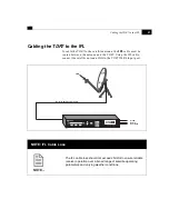
Cabling the Fault Relay Port
Cabling the Fault Relay Port
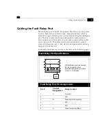
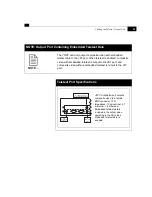
The fault relay port is an RJ–45 connector that allows you to create a
Form–C fault relay to indicate a non–normal condition, which is
defined as a power failure, power switch turned off, or an unplugged
unit. The non–normal condition is indicated by contact closure
between pins one (1) and three (3), and open contacts between pins
one (1) and six (6). The normal condition is indicated by contact
closure between pins one (1) and six (6), and open contacts between
pins one (1) and three (3).
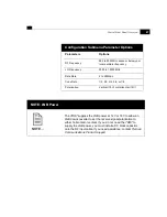
Fault relay port pinouts are listed in the table on the following page.
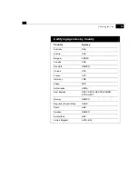
Fault Relay Port Specifications
Fault Relay Port Pin Assignments
Pin #
Contact
Designation
Relay Contact
1
C
Common
2
N/ C
3
B
Closed for fault condition
4
N/ C
5
N/ C
6
A
Open for fault condition
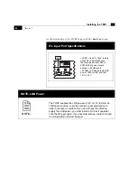
J5 fault relay
port is a female
RJ–45 connector which
provides connections to create
a Form–C fault relay.
D1 Video
Remote Control Fault Relay
J5
Fault
Relay
Содержание TDR7
Страница 17: ...Chapter 1 TDR7 Overview...
Страница 18: ......
Страница 25: ...Chapter 2 Installing the TDR7...
Страница 26: ......
Страница 48: ...Chapter 2 34 Installing the TDR7...
Страница 49: ...Chapter 3 Using the Control Front Panel...
Страница 50: ......
Страница 78: ......
Страница 79: ...Chapter 4 Using a Remote Control Device Interface...
Страница 80: ......
Страница 111: ...Chapter 5 Configuring the TDR7...
Страница 112: ......
Страница 151: ...Chapter 6 Troubleshooting...
Страница 152: ......
Страница 169: ...157 Appendixes Maintenance Glossary Warranty Specifications and Index...
Страница 170: ...I...
Страница 176: ...164 Maintenance...


