background image

157

Appendixes

Maintenance, Glossary, Warranty,
Specifications, and Index

Содержание TDR7

Страница 1: ...ect Select STATUS FAULT POWER MPEG 2 Encoder Previous More Communications 1 2 3 4 5 6 7 8 9 0 Select Enter Select Select STATUS FAULT POWER IRD MPEG2 TDR7 MPEG DVB Receiver Decoder Copyright 1998 1999...

Страница 2: ...l To properly install and operate this equipment and or all parts thereof personnel must strictly and explicitly follow all of the instructions in this manual FAILURE TO COMPLETELY READ AND FULLY UNDE...

Страница 3: ...ns Inc 5751 Copley Drive San Diego CA 92111 U S A No Warranty The contents of this manual are provided as is without warranty of any kind either expressed or implied including but not limited to the i...

Страница 4: ...tial damages so the above limitation or exclusion may not apply to you For further information on legal and intellectual property matters contact Tiernan Communications Corporate Counsel WARNING Elect...

Страница 5: ...thin Systems 9 Chapter 2 Installing the TDR7 13 Placement 14 Ventilation 14 Table Top Placement 14 Rack Mount Placement 15 Powering the Unit 17 AC Power Cords 18 North American Applications 18 Interna...

Страница 6: ...te Control Device Interface 69 Remote Control Device Overview 70 Entering Commands 70 Error Messages 74 RCD Commands 75 Audio Decoder Channel A ADA and Channel B ADB Commands 76 Decoder Control DC Com...

Страница 7: ...bleshooting 141 BIST Functions 141 Demodulator Status 143 Fault Monitoring 145 Event Time Tagging 145 Current Faults 146 Fault History 147 Output Observation 150 Solving Problems 151 Appendixes Mainte...

Страница 8: ...Support 175 Contacting Tiernan Communications Product Support 176 Telephone and Fax Numbers 177 E mail Address 177 Returning Units 178 Tiernan Service Procedure for Out of Warranty Repairs 179 TDR7 S...

Страница 9: ...l tasks Additionally it contains overviews of the system operation as well as technical specifications and troubleshooting procedures A statement of the Tiernan warranty policy a list of customer serv...

Страница 10: ...that requires special attention to detail or poses the possibility of injury excluding injury resulting from electric shock NOTE The Note symbol identifies points of interest or information relevant...

Страница 11: ...s that appear in bold are defined in the Glossary Units of Measure Text in san serif oblique typeface represents units of measure LCD and Remote Terminal Displays Text in monospace typeface represents...

Страница 12: ...ntroduction control front panel and remote control information Revision D 08 28 96 Revised the TDR7 external connections and the introduction installation and startup control front panel and system in...

Страница 13: ...mware v 2 24 02 Revision I 10 05 97 Revised to include teletext port specifications and cabling instructions addition of user data channel and fault relay remote control commands updated user data men...

Страница 14: ...s If any part of your shipment is missing call Tiernan Communications Product Support at 619 587 0252 or send a fax to 619 587 0257 For immediate assistance call our 24 hour customer service paging sy...

Страница 15: ...oth specially designed suspension frames are available for use in repacking the equipment The suspension frames look like a cardboard frame with a sheet of clear plastic stretched over the opening 3 I...

Страница 16: ...carton and onto the center of the plastic suspension frame 3 Place the second suspension frame into the shipping carton with the plastic film side facing down towards the top of the equipment The plas...

Страница 17: ...Chapter 1 TDR7 Overview...

Страница 18: ......

Страница 19: ...ect Select STATUS FAULT POWER MPEG 2 Encoder Previous More Communications 1 2 3 4 5 6 7 8 9 0 Select Enter Select Select STATUS FAULT POWER IRD MPEG2 Feature Set DVB and MPEG 2 compliant signal input...

Страница 20: ...ssed Teletext data parameters are configurable from the control front panel using an added menu or from a remote control device using configuration commands Variable compressed video and audio bit rat...

Страница 21: ...remote control device Procedures for configuring and monitoring the TDR7 are described in Chapter 3 for the control front panel and in Chapter 4 for the remote control device In and output connectivi...

Страница 22: ...rminal emulation program with bisynchronous communications at standard baud rates Remote control device installation instructions are detailed in Chapter 2 and operating instructions are detailed in C...

Страница 23: ...video bit rates from 1 15Mbps and audio bit rates from 32 384Kbps Operation within Systems The TDR7 supports both single channel per carrier SCPC and multi channel per carrier MCPC operations and can...

Страница 24: ...the TTO 6000 option module teletext data may be included in the video output while in the PAL mode With the TEA 6000 option module up to four AES EBU audio channels are automatically embedded in the d...

Страница 25: ...Chapter 2 Installing the TDR7...

Страница 26: ......

Страница 27: ...nsport Output RF IN IEC Power Cord Receptacle Cooling Fan Exhaust On Off Switch J12 Audio A J3 Audio B J4 D1 Digital Video J13 Composite Video J10 Transport Input J5 Fault Relay J11 User Data A B J50...

Страница 28: ...he TDR7 is placed on a table or other flat surface the small peel and stick rubber feet which are provided in the standard shipping kit should be affixed to the bottom corners of the chassis to preven...

Страница 29: ...mount brackets on both sides of the front panel 3 If you ordered and intend to use the optional rack mount slides use the supplied hardware to install the slides Instructions for installing the rack...

Страница 30: ...ts to the standard equipment rack using the hardware provided in the optional rack mount slides shipping kit Next attach the sliders to the TDR7 chassis using the hardware provided in the optional rac...

Страница 31: ...h 0 IEC Power Cord Receptacle On Off Switch Cooling Fan Exhaust The TDR7 unit is powered by an auto sensing auto ranging AC switching power supply that accepts 80 to 265VAC input voltage levels at 50...

Страница 32: ...s an IEC compatible female plug on one end and three stripped and tinned bare wires on the other end This cord is for international applications and is approved up to 250VAC at 6A by many internationa...

Страница 33: ...alia SAA Austria OVE Belgium CEBEC Canada CSA Denmark DEMKO Finland UTE France UTE Germany VDE Japan MITI Netherlands KEMA New Zealand SECV SECQ SECWA EANSW ETSA HECT Norway NEMKO Republic of South Af...

Страница 34: ...ground symbol or colored green and yellow 2 The blue wire must be connected to the terminal marked with the letter N or colored black 3 The brown wire must be connected to the terminal marked with th...

Страница 35: ...Audio User Data LNB IFL Inter Facility Link Cable Previous More Communications 1 2 3 4 5 6 7 8 9 0 Select Enter Select Select STATUS FAULT POWER MPEG 2 Encoder Previous More Communications 1 2 3 4 5 6...

Страница 36: ...dance that accepts RF from 950 to 2050MHz at power levels between 85 dBm and 20dBm J50 also outputs LNB power 500mA DC at either 12V or 18V NOTE LNB Power The TDR7 supplies the LNB power at 12V or 18V...

Страница 37: ...NTSC and BT 470 CCIR Report 624 for PAL and are described below Video Ports Specifications J13 Composite outputs composite video to a female BNC connector 75 impedance 1Vpp nominal 0 7 minimum 1 4 ma...

Страница 38: ...tions Audio Output Ports Pin Assignments Pin Signal Direction 1 Aud_L input 2 Aud_L input 3 AESEBU input 4 Aud_R input 5 Aud_R input 6 7 GND 8 AESEBU input 9 GND Composite Audio A Audio B D1 Video J12...

Страница 39: ...s and the synchronous user data channel can operate up to 4 096Mbps Pinouts for the user data port connector are listed in the table below User Data Port Specifications J11 Data A B port is an RS 449...

Страница 40: ...Output Clock 2 RDA Output Receive Data A 3 RRA Output Signaling 4 RDB Output Receive Data B 5 RTB Output Clock 6 RTA Output Clock 7 RDA Output Receive Data A 8 RRA Output Signaling 9 GND 10 RTB Outpu...

Страница 41: ...ish and multiple IRDs The transport stream input port pinouts are listed in the table below Transport Input Port Specifications Transport Input Port Pin Assignments Pin Signal 1 RD 3 TXD 6 RD 8 RR 9 G...

Страница 42: ...a a DVB ASI compliant port labeled J51 which is described below Transport Output Port Specifications J51 Transport Output port provides a DVB ASI compliant transport stream on a female BNC connector 7...

Страница 43: ...tion installed or a network management system host computer with a bisynchronous communications protocol Both the asynchronous and the bisynchronous communications protocols are embedded in the TDR7 f...

Страница 44: ...mpt at the RCD follow the troubleshooting steps defined in the Solving Problems section of Chapter 6 4 Once communications have been established between the RCD and the TDR7 you can change the RCD por...

Страница 45: ...ween pins one 1 and six 6 The normal condition is indicated by contact closure between pins one 1 and six 6 and open contacts between pins one 1 and three 3 Fault relay port pinouts are listed in the...

Страница 46: ...ext data you should connect your video equipment to the J61 composite video port however if you change video operating modes from PAL to NTSC you must move the cable connecting the TDR7 to your video...

Страница 47: ...composite video without embedded teletext is output to the J13 port NOTE Teletext Port Specifications J61 Composite port outputs composite video to a female BNC connector 75 impedance 1Vpp nominal 0...

Страница 48: ...Chapter 2 34 Installing the TDR7...

Страница 49: ...Chapter 3 Using the Control Front Panel...

Страница 50: ......

Страница 51: ...rked I which is the on position The LED labeled Power on the control front panel illuminates in green and the LCD displays Initializing for a few seconds After the unit is initialized the LCD displays...

Страница 52: ...and the Inc up and Dec down buttons are located near the middle of the control front panel The Inc up and Dec down buttons are not labeled LED indicators are located on the lower right side of the co...

Страница 53: ...splays in the right side of the LCD to indicate that you can access other menus by pressing the More button Main Menu Overview The first main menus displayed by the LCD are the System Demod and Faults...

Страница 54: ...d to clear the fault history log Video menu Allows you to select the video mode Audio menu Allows you to set the volume for the audio output channels Data menu Allows you to set the data rate for the...

Страница 55: ...ing the control front panel VBI menu Allows you to display and select the teletext PIDs available in the selected service Additionally if teletext data is available in the selected service you can det...

Страница 56: ...own in a black box Selectable parameters or submenus of the main menu are shown below the main menu A large down pointing arrow under a main menu or between parameters or submenus indicates that you m...

Страница 57: ...t configuration parameters but you can t change them Locking the control front panel prevents someone from accidentally changing your configuration settings Complete instructions on locking and unlock...

Страница 58: ...ys a measurement in MHz of the difference between the actual receive carrier frequency and the frequency determined by subtracting the LO Freq parameter from the RF Freq parameter To achieve carrier t...

Страница 59: ...Rate 1 2 2 3 3 4 5 6 or 7 8 Polarization Vertical 18V or Horizontal 12V NOTE LNB Power The TDR7 supplies the LNB power at 12V or 18V to allow an LNB downconverter to set the receive signal polarizatio...

Страница 60: ...play one at a time beginning with the most recent fault If more than one current fault exists or the fault history log contains more than one fault the LCD displays a right pointing arrow in the right...

Страница 61: ...means that it automatically changes the video parameters to match those of the input signal NOTE Changing Video Modes While Processing Teletext Data If your TDR7 has a TTO 6000 option module installe...

Страница 62: ...audio level which means that the volume control cannot increase or amplify the incoming audio level Use the keypad to set the volume to a value between 0 to 100 Menu Audio Volume Audio A Volume Audio...

Страница 63: ...submenu allows you to set the Data Rate for a synchronous user data channel in bits per second The Async submenu allows you to configure the Baud rate number of Data Bits Parity and number of Stop Bit...

Страница 64: ...rs are in a 24 hour format and must be set from 00 to 23 where 00 is midnight and 23 is 11 PM For example for 8 AM you would set 08 and for 8 PM you would set 20 Both the minutes and the seconds can b...

Страница 65: ...clears the fault history log whenever you reset the unit If you are experiencing problems and decide to reset the unit first go to the History function and write down all faults contained in the faul...

Страница 66: ...ream input is provided the LCD displays the message None PGCA Menu The PGCA menu contains three functions Status Authorization and Timeout on loss The Status function displays whether or not the selec...

Страница 67: ...vice in the event that the TDR7 loses the incoming service signal The Timeout on loss is measured in seconds but the service originator can set it to allow the service to remain authorized endlessly N...

Страница 68: ...lects the teletext PID available in the selected service The Mode function allows you to determine whether the teletext data will be included in the video output stream Unless you select On the telete...

Страница 69: ...teletext data your video output equipment must be cabled to the J61 teletext port on the back of the TDR7 Before you begin to reconfigure the TDR7 to process teletext data you should ensure that your...

Страница 70: ...Chapter 3 58 Using the Control Front Panel Version Menu The Version menu contains the Firmware function that displays the version of firmware used in your unit Menu Version Firmware...

Страница 71: ...located directly below it When you select a menu item or a function the TDR7 either advances to a submenu or allows you to select a parameter for alteration LED Indicators Keypad Menu Buttons Previou...

Страница 72: ...button the unit returns to the System Demod and Faults menus Display Format Except for error messages faults the LCD displays entries in the format shown below The example below shows that the data r...

Страница 73: ...the LCD displays a fault stored in the fault history log Error messages are explained in detail in Chapter 6 of this manual Previous More Communications Select Select Select Previous More Communicatio...

Страница 74: ...ith the keypad others can be changed by using the Inc up or Dec down buttons to scroll through a list of options then selecting the option you want To set an option press the Inc up or Dec down button...

Страница 75: ...e with the keypad you can press the Inc up button to change the value to 0 then enter the correct value or press the Dec down button to delete the numbers If you are selecting an option from the list...

Страница 76: ...der the Demod menu 2 The LCD displays the Config and Status menus 3 Press the Select button located directly under the Config menu Previous More Communications Select Select Select Previous More Commu...

Страница 77: ...e parameter press the Enter button located near the middle of the TDR7 control front panel 7 Press the Previous button located to the left side of the LCD twice to return to the top level menus Settin...

Страница 78: ......

Страница 79: ...Chapter 4 Using a Remote Control Device Interface...

Страница 80: ......

Страница 81: ...ol device capable of asynchronous communications at RS 232 electrical levels The RCD provides full duplex operations with the TDR7 so that whenever you type a keystroke on the RCD it issues an asynchr...

Страница 82: ...You must start each command with a command mnemonic This is typically followed by a first level mnemonic which further specifies the command First level mnemonics may be followed by other mnemonics r...

Страница 83: ...ensitive You may enter the commands in lower case upper case or a combination of both NOTE Displaying the Current Status or Setting of a Functional Block or Parameter To display the current status or...

Страница 84: ...ume to a specific parameter the TDR7 receives the command as a query and responds by sending the current setting for the audio volume of Channel A to the RCD which displays the information The command...

Страница 85: ..._VOL_80 Loading Audio Decoder A After the TDR7 has set the parameter the prompt displays to indicate that the TDR7 is ready for the next command If you want to verify that the TDR7 set the parameter y...

Страница 86: ...the TDR7 execute the command contact Tiernan Communications Product Support Format Error The command string was entered with extra characters or in an improper order Most commonly an extra space was e...

Страница 87: ...f the mnemonic within the command When entering commands at the RCD enter either the mnemonic or its numerical equivalent not both For example to send a query command to view the list of audio PIDs av...

Страница 88: ...ue between 0 and 100 of the incoming audio level which means that the volume control cannot increase or amplify the incoming audio level The DVB default is 100 DELAY 20 Compressed audio stream buffer...

Страница 89: ...unction ADA Audio Channel A PID 1 Displays a list of audio PIDs available in channel A 00 FF Enter the PID number for the audio you want to select The TDR7 defaults to the first audio PID in the selec...

Страница 90: ...Displays a list of PMT PIDs available in the selected service 32 8190 Enter the number of the PMT PID you want to select PROG Displays a list of services available in the transport stream Enter the nu...

Страница 91: ...e or firmware versions of the audio video and master controllers Entering the DV command mnemonic queries the TDR7 for the current MPEG decompressor software version DV Command List First Level Mnemon...

Страница 92: ...ported real time which means that only conditions that are present at the time that you enter the FC command are displayed regardless of what conditions have existed in the past If the current fault c...

Страница 93: ...nent of the TDR7 and ending in a fault descriptor For example if the input source to the video decoder is interrupted or disconnected the RCD displays 15 23 17 day 21 VD FIFO Idle after you enter FH I...

Страница 94: ...e fault relay If you have not wired a fault relay the TDR7 displays FR NOFAULT when you enter the FR command FIFO Status FS Command Entering the query command FS displays the first in first out FIFO b...

Страница 95: ...ialize all of the functional blocks shown below enter the IN command To initialize one of the functional blocks type the IN command followed by the appropriate first level mnemonic IN Command List Fir...

Страница 96: ...t First Level Mnemonic Second Level Mnemonic Third Level Mnemonic Effected Functions RS232 0 RS 232 remote control port configuration BAUD 1 Asynchronous interface baud rate 1200 1200 baud DVB default...

Страница 97: ...alization ON 1 Enable auto initialization DVB default NOTE Changing RCD Port Parameters To change the parameters of your RCD port issue the appropriate Master Control command at the RCD prompt After t...

Страница 98: ...te control device to change the TDR7 operating mode or configuration the changes are not automatically stored in non volatile flash memory Whenever you change your configuration using a remote control...

Страница 99: ...ected service If the service is authorized the RCD displays Yes if the service is not authorized the RCD displays No If no transport stream input is provided the RCD displays N A Timeout Displays the...

Страница 100: ...rate to 1 2 2 3 Sets Viterbi code rate to 2 3 3 4 Sets Viterbi code rate to 3 4 5 6 Sets Viterbi code rate to 5 6 DVB default 7 8 Sets Viterbi code rate to 7 8 DR Displays the current transport strea...

Страница 101: ...ce between the actual receive carrier frequency and the frequency determined by subtracting the LO Freq parameter from the RF Freq parameter To achieve carrier transport stream lock the difference bet...

Страница 102: ...12VDC or 18VDC which allows an LNB downconverter to set the receive signal polarization to either horizontal or vertical If you do not need the TDR7 to supply the LNB power you must install a DC bloc...

Страница 103: ...s to 00 00 00 Day 0 whenever you reset the TDR7 or turn the power off and then back on After you reset the unit or turn the power on use the TI command to set the current day and time NOTE Before You...

Страница 104: ...ype in the current hour minutes seconds and day separating each category with a colon then press the Enter key To make a change to the day or any aspect of the time you must enter the entire command s...

Страница 105: ...this manual Terminate Diagnostic TD Command The TD command allows you to stop a diagnostic that is running To stop the diagnostic once the RD command has been issued type TD and press the Enter key N...

Страница 106: ...Level Mnemonic Second Level Mnemonic Third Level Mnemonic Fourth Level Mnemonic Effected Function PID Displays a list of user data channel PIDs available in the selected service 0 8191 Enter the PID...

Страница 107: ...ce 50 75 110 150 300 600 1200 2400 360 4800 7200 9600 19200 38400 56000 or 115200 Enter the asynchronous interface baud rate for the user data channel The DVB default is 38400bps DATABITS Displays the...

Страница 108: ...arity for user data channel The DVB default is N STOPBITS Displays the number of stop bits for user data channel asynchronous interface 1 or 2 Enter the number of stop bits for the user data channel a...

Страница 109: ...ent TTO 6000 option module configuration VBI Command List First Level Mnemonic Second Level Mnemonic Third Level Mnemonic Effected Function Teletext TTO 6000 VBI data Mode On Teletext data will be inc...

Страница 110: ...C format PAL 1 PAL format DVB default DELAY 20 Allows you to set the delay between the time the video data is received and the time the video data is sent to the video output port to compensate for th...

Страница 111: ...Chapter 5 Configuring the TDR7...

Страница 112: ......

Страница 113: ...hannels the composite and digital video channels and user data channel A to be decoded and decompressed at the DVB default rates When set to DVB defaults user data channel B is disabled Unless your si...

Страница 114: ...ted the TDR7 defaults to the first authorized service detected in the transport stream Video Decoder DVB Defaults Parameter Setting Video PID Defaults to the first video channel detected in the select...

Страница 115: ...cally switches to it Audio Volume 100 Audio PID Defaults to the first audio channel detected in the selected service Audio Auto Detect On User Data Channels DVB Defaults Parameter Setting Interface Ty...

Страница 116: ...de to on the unit selects the first active line of Teletext data detected in the selected service Maximum Number of Teletext Lines 16 lines per field or 32 lines per frame NOTE Maximum Number of Telet...

Страница 117: ...itionally the TDR7 automatically selects the first available service and the first available PIDs in the selected service which means that audio video and user data are output immediately without need...

Страница 118: ...to 18V If the incoming signal is horizontally polarized you must set the LNB power parameter to 12V NOTE Video and Audio Operating Parameters In the TDR7 both the video decoder and the audio decoder a...

Страница 119: ...u press the Enter button an asterisk displays and flashes for a few seconds in the upper right corner of the LCD When the asterisk disappears the TDR7 has set the parameter To restore the TDR7 to DVB...

Страница 120: ...DVB defaults the demodulator parameters also revert to the DVB defaults Unless your incoming signal frequency and polarization LO frequency Viterbi code rate and transport stream data rate parameters...

Страница 121: ...oming RF Frequency 11 774 GHz 11774MHz Transmission Data Rate 8 448 Mbps Viterbi Code Rate 3 4 Signal Polarization Vertical To configure the TDR7 demodulator parameters perform the steps listed below...

Страница 122: ...te 1 The LCD displays 8448000bps which is the DVB default setting for the data rate parameter Because the data rate of the incoming RF signal matches the DVB default setting you don t need to change t...

Страница 123: ...that you set the correct frequency then press the More button to display and verify each of the other Config parameters After you have verified your entries the demodulator is configured and you shoul...

Страница 124: ...ur TDR7 is authorized to receive the service To view the selected service select the Service main menu The LCD displays the current service If the LCD displays No Services Available or None verify tha...

Страница 125: ...TDR7 has set the parameter 1 If the LCD is not displaying the System menu press the Previous button until the LCD displays the System menu 2 Press the More button until the LCD displays the Service me...

Страница 126: ...il the service you want displays then press the Enter button 5 Press the Previous button to return to the main menus MCPC Service Selection Cont Previous More Communications Select Select Select Previ...

Страница 127: ...le teletext data along with the commands for viewing the teletext lines and PID detected in the selected service are shown below To enable teletext data 1 If the LCD is not displaying the System menu...

Страница 128: ...tive Line submenu 5 The LCD displays the teletext lines that are being inserted into the transport stream by the encoder To view the teletext PID available in the selected service 1 If the LCD is not...

Страница 129: ...ront Panel NOTE Saving Configurations The TDR7 automatically saves any configuration changes performed using the control front panel Whenever the power is turned on or the unit is reset the TDR7 resto...

Страница 130: ...er Setting the Day The day must be set as a number between 1 and 31 1 If the LCD is not displaying the System menu press the Previous button until the System menu displays 2 Press the More button unti...

Страница 131: ...ss the Previous button until the System menu displays 2 Press the More button until the LCD displays the Control main menu then press the Select button located directly under the Control menu The LCD...

Страница 132: ...TDR7 has set the parameter 1 If the LCD is not displaying the System menu press the Previous button until the System menu displays 2 Press the Select button located directly under the System menu The...

Страница 133: ...corner of the LCD When the asterisk disappears the TDR7 has set the parameter 1 If the LCD is not displaying the System menu press the Previous button until the System menu displays 2 Press the Selec...

Страница 134: ...playing the System menu press the Previous button until the System menu displays 2 Press the Select button located directly under the Demod menu The LCD displays the Config and Status functions 3 Pres...

Страница 135: ...the Select button located directly under the Demod menu The LCD displays the Config and Status functions 3 Press the Select button located directly under the Status function The LCD displays Eb No fol...

Страница 136: ...located directly under the Demod menu The LCD displays the Config and Status functions 3 Press the Select button located directly under the Status function The LCD displays Eb No followed by the curre...

Страница 137: ...dicating that you can press the More button to display the additional faults To view the fault history log 1 If the LCD is not displaying the System menu press the Previous button until the System men...

Страница 138: ...configuration changes you should need to make to the TDR7 to begin operations include Configuring the TDR7 to either DVB or NTL settings Configuring the demodulator to match the incoming RF signal Sel...

Страница 139: ...E Video and Audio Operating Parameters Both the TDR7 video and audio decoders are fully auto detecting which means that the TDR7 automatically sets all of the video and audio parameters required for o...

Страница 140: ...trol device As the parameter settings you need depend upon your operational requirements examples that exactly match your needs may not be included If that is the case use these examples as guidelines...

Страница 141: ...in MHz convert the frequency to MHz 2 The local oscillator frequency of your LNB downconverter This frequency is typically posted somewhere on the equipment or in the manufacturer s documentation If t...

Страница 142: ...O frequency At the RCD prompt type QD_LO_11300 then press the Enter key To set the transport stream data rate At the RCD prompt type QD_DR_7000000 then press the Enter key To set the Viterbi code rate...

Страница 143: ...the parameters are correct After you have verified that the demodulator parameters are set correctly you should begin receiving flawless video and audio If you are not receiving flawless video and au...

Страница 144: ...R7 parameters to DVB defaults the demodulator parameters also revert to the DVB defaults Unless your incoming signal frequency and polarization LO frequency Viterbi code rate and transport stream data...

Страница 145: ...re the TDR7 parameters to NTL defaults the demodulator parameters also revert to the NTL defaults Unless your incoming signal frequency and polarization LO frequency Viterbi code rate and transport st...

Страница 146: ...ignal the TDR7 automatically selects the first available service in the MCPC signal and provides audio video and user data outputs If you want to select a different service you must select one from th...

Страница 147: ...CD prompt type DC_ADA_PID then press the Enter key To select an audio PID In this example assume that you want to select audio PID number 32 At the RCD prompt type DC_ADA_PID_32 then press the Enter k...

Страница 148: ...7 then press the Enter key If you want to view or select PIDs for user data channel B issue the same commands as for channel A but substitute UDB as the first level mnemonic Once you have selected the...

Страница 149: ...eletext data At the RCD prompt type VBI_MODE_ON then press the Enter key To view teletext lines detected in the selected service At the RCD prompt type VBI_LINE then press the Enter key To view the te...

Страница 150: ...d in Chapter 6 of this manual To view demodulator lock status At the RCD type QD_LOCK_DEMOD then press the Enter key To view decoder lock status At the RCD type QD_LOCK_DECODER then press the Enter ke...

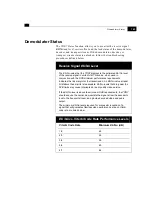
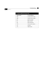
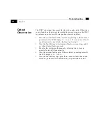
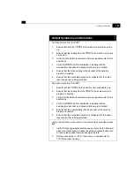
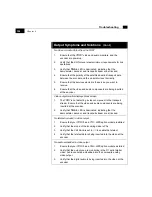
Страница 151: ...Chapter 6 Troubleshooting...

Страница 152: ......

Страница 153: ...ng diagnostic functions status parameters and fault monitoring BIST Functions Using the TDR7 internal micro controller you can perform several built in self test BIST functions The self tests are perf...

Страница 154: ...decoder and transport stream are all locked OFF If the Status LED is not illuminated at least one of the following is unlocked demodulator decoder or transport stream Perform the procedures described...

Страница 155: ...rformance requirements indicates the link margin for the transmission An Eb No value at least 3dB above these limits is reasonable Eb No levels that drop near the DVB limits may cause interrupted or p...

Страница 156: ...ter from the RF Freq parameter To achieve carrier transport stream lock the difference between the two frequencies or the Offset must be less than 2MHz however to achieve optimum performance the Offse...

Страница 157: ...ain menu This section describes how the TDR7 reports faults and how to use the Current and History functions to isolate hardware and operational problems Event Time Tagging The TDR7 maintains an inter...

Страница 158: ...ays No Faults after you select the Current submenu However every current fault is recorded in the fault history log If the Status LED on the control front panel is illuminated no current faults exist...

Страница 159: ...er a fault is detected it is stored in volatile memory until one of the following events occur The TDR7 power is turned off The TDR7 is reset You clear the fault history log by typing FH_0 Faults stor...

Страница 160: ...tional Block Designators Abbreviation Functional Block ADA Audio Decoder Channel A ADB Audio Decoder Channel B DC Decoder Controller MC Master Controller QD QPSK Demodulator TTO Teletext Insertion Mod...

Страница 161: ...utput clock too fast or input clock too slow HW Fault Abnormal hardware condition detected Hardware failure or incorrect configuration Initialize Functional block initialization failure Corrupted conf...

Страница 162: ...ers the LCD displays No Faults If a one or more fault conditions exist annotate the fault and go to step 2 2 View the fault history to determine if faults are occurring and if so when the last fault o...

Страница 163: ...that your LNB downconverter is properly oriented to the polarization of the incoming RF signal 4 Determine if the IFL cable loss exceeds 25dBm 5 Ensure that all installation cables are connected prope...

Страница 164: ...l levels are above the minimum DVB limits If the Eb No and receive signal levels are sufficient confirm that the RF frequency RF Freq local oscillator frequency LO Freq transport stream data rate Data...

Страница 165: ...TDR7 and the audio monitor are powered up 2 Ensure that the cabling from the TDR7 to the audio monitor is properly connected 3 Verify that the Eb No level meets minimum requirements for link operatio...

Страница 166: ...a video component in the transport stream Ensure that the video and audio components are being inserted at the encoder 2 Verify that Status LED is illuminated indicating that the demodulator decoder...

Страница 167: ...TTO FIFO Errors If TTO FIFO error conditions occur more than three times within 60 seconds the TDR7 reduces the maximum number of teletext data from 16 to 15 lines per field or from 32 to 31 lines per...

Страница 168: ...bisynchronous communications 5 Ensure that the RCD and the TDR7 are powered up 6 Use the control front panel to configure the TDR7 to the DVB defaults For procedures on configuring the TDR7 to the DV...

Страница 169: ...157 Appendixes Maintenance Glossary Warranty Specifications and Index...

Страница 170: ...I...

Страница 171: ...gate array FPGA configuration files For upgrading software and configuration files in the field the memory can be accessed through the remote control port of the TDR7 You can perform field software up...

Страница 172: ...rectly from the Tiernan web site you must have a computer with the capability of downloading files via the Internet Additionally your computer must have sufficient storage capacity to store the softwa...

Страница 173: ...tep by step upgrading instructions Downloading the Software From the Web Site An overview of the procedures you will follow to download the software files from the Tiernan web site is listed below 1 E...

Страница 174: ...ations Product Support engineer s instructions for transferring the software upgrade files to the TDR7 Upgrading from a Floppy Disk The basic process used to perform a field software upgrade of the TD...

Страница 175: ...o transfer the software files to the TDR7 is listed below 1 Write down your current TDR7 configuration After you have performed the software upgrade and have loaded the software into the TDR7 you will...

Страница 176: ...164 Maintenance...

Страница 177: ...of an incoming signal Auto ranging The capability of a power supply unit to accept variable voltage rates Auto sensing The capability of a power supply unit to detect variable voltage rates B Baseban...

Страница 178: ...ational state C C band A portion of the electromagnetic spectrum used heavily for satellite transmissions The uplink frequency is at 6GHz and the downlink is at 4GHz Traditional applications include v...

Страница 179: ...r wave DS3 A commercial leased line that has the capacity to handle up to 44 763Mbps of digital information dsec Deci seconds A measurement of time that is equal to 0 1 seconds For example 15dsec is e...

Страница 180: ...signals from an earth terminal to a satellite I IEC International Electrotechnical Commission A Geneva based organization that sets international electrical and electronics standards and includes nati...

Страница 181: ...rect Broadcast Satellite DBS systems or Direct Satellite System DSS Kbps Kilobits per second A ratio of 1000 bits transmitted per second For example 10Kbps is equal to 10 000 bits transmitted per seco...

Страница 182: ...contained in a stereo mix MPEG Moving Picture Experts Group A joint committee of the International Standards Organization ISO and the International Electrotechnical Commission IEC 2 A series of hardwa...

Страница 183: ...ned at the rate of 30 frames per second 3 Used to describe the standard method of television transmission in the U S Canada japan Central America and parts of South America O Ohm A unit of measure for...

Страница 184: ...ion Pixel Picture Element 1 The smallest unit of area of a video screen image that can be turned on or off or varied in intensity 2 The smallest division that makes up the raster scan line for a video...

Страница 185: ...og signal is measured and converted to a binary number to seconds elapsed expressed as samples per second 2 Symbols per second A ratio of symbols transmitted to seconds elapsed expressed as symbols pe...

Страница 186: ...ons Inc internal multiplexer that allows an encoder to multiplex various inputs into a single MPEG 2 transport stream output TTM 2070 RA A Tiernan Communications Inc option module that allows an encod...

Страница 187: ...e whether proper operation may be restored with instruction over the phone Should it be necessary to return the TDR7 to Tiernan for analysis you must obtain a Return Materials Authorization RMA number...

Страница 188: ...d to provide and discuss the following information The Tiernan product name Product software version Product serial number Date equipment was installed Date equipment failed System configuration SCPC...

Страница 189: ...me Company Phone number If you are calling from outside of the U S please include 011 and the Country Code as part of your phone number Fax number if you want us to return your call via fax E mail add...

Страница 190: ...or application alteration accident or negligence in use storage transportation or handling 6 Any returned product shall be completely evaluated in an attempt to duplicate the problem so that appropri...

Страница 191: ...stances which may have led to the problem This information is essential for Tiernan repair technicians to reproduce diagnose and correct the problem 4 If the unit is being returned for modification pl...

Страница 192: ...d repaired Following repair the unit will be thoroughly tested for compliance with appropriate specifications This process will be handled in an expedient and prompt manner but may be subject to avail...

Страница 193: ...tectable Compressed video bit rates from 1Mbp to 15Mbps Horizontal resolutions of 720 544 480 352 pixels per line Vertical resolutions of NTSC 240 480 and PAL 288 576 Horizontal and vertical filtering...

Страница 194: ...B 9 connector at up to 38 4Kbps Physical Specifications 3 5 inches 88 2mm high 18 6 inches 472 5mm deep 16 8 inches 425 2mm wide LNB Power 18V or 12V direct current supplied on the IFL cable allows LN...

Страница 195: ...Function 45 Default setting 104 Active Line Teletext default 104 Active Line Function Displaying available teletext lines 56 Teletext 56 ADA ADB Command List 76 AGC 88 Antenna 151 Arrow in LCD explai...

Страница 196: ...efault setting 103 Authorization Defined 87 Displaying with an RCD 87 Authorization Function 54 Defined 54 Displaying whether service is authorized 54 Authorization to receive a service 55 Authorized...

Страница 197: ...lock 52 53 Current time and day with an RCD 92 Day format 92 Resetting 91 Run time 92 Time Format 52 92 Clock Function 52 Setting Day with control front panel 118 Time with control front panel 119 Cod...

Страница 198: ...Function 48 Displaying current faults 48 D Data A Submenu 51 Data B Submenu 51 Data Bits Asynchronous user data channel parameter options 51 Configuring async user data channel with an RCD 95 Default...

Страница 199: ...g 101 Configuring 109 Code rate with control front panel 109 Data rate with control front panel 109 RF frequency with control front panel 109 Signal polarization with control front panel 109 With an R...

Страница 200: ...r 101 Demodulator data rate 101 List of channels enabled 101 Listed 101 LNB polarization 101 LNB power 101 LO frequency 101 Maximum number of Teletext lines 104 Operating with 101 Parity 103 Remote co...

Страница 201: ...l with control front panel 51 Embedded Audio 5 Troubleshooting 154 Entering Commands with an RCD 70 Error Messages 74 Error messages Display format 61 Event time tagging 145 Examples Configurations wi...

Страница 202: ...IRD with control front panel 122 Unlocking the control front panel 121 Execute commands defined 70 External connections 8 F Fault Current FC Commands 80 Fault Descriptors 149 Bad Eb No 149 FIFO idle 1...

Страница 203: ...urrent defined 80 146 Descriptors 149 Event time tagging 145 Fault LED 81 Function block designators 148 History and logging 147 History log 81 History log display format 81 147 Loss of decoder sync f...

Страница 204: ...plained 62 Form C fault relay Installing 31 Fourth level mnemonics defined 70 FS Command 82 Functional Block Designators 148 Functional block initialization failure 149 Functional Blocks Audio Decoder...

Страница 205: ...power cords North American applications 18 Audio port pin assignments 24 Cabling Fault relay 31 IFL 21 Teletext output port 33 User equipment to audio output ports 24 User equipment to data output po...

Страница 206: ...ut pin assignments 27 User data port pin assignments 26 Ventilation 14 Wiring plugs with non corresponding color codes 20 Interface Type Default setting 103 Interfaces AC power supply 17 Remote contro...

Страница 207: ...explained 152 Indicating after self tests 142 Indicating no services available 112 Not illuminated explained 152 Limitation of Liability iv Line Displaying teletext lines available in selected servic...

Страница 208: ...ault 80 146 Loss of demodulator sync fault 80 146 Loss of transport stream sync fault 80 146 M Main Menus Audio 50 Control 52 Data 51 Defined 41 Demod 46 Descriptions 44 Faults Menu 48 Moving through...

Страница 209: ...n RCD 86 Menus 41 Async 51 Faults menu 48 Intf 51 Moving through 59 Overview of main menus 41 Sync 51 Messages Access Denied 74 Bad Eb No 149 Error 74 Fault log empty 81 147 FIFO idle 149 FIFO Ovrflw...

Страница 210: ...No Warranty Statement iii Non volatile field programmable memory 4 None message 54 North American power cord 18 NTL Configuration Restoring with an RCD 85 NTL Defaults Configuring to with an RCD 133...

Страница 211: ...for asynchronous user data channel 51 Parity Function Default setting 103 PCR Selecting PID with an RCD 78 PGCA 54 PGCA Command List 87 PGCA Commands 87 PGCA Menu 54 Physical function 51 PID Audio PID...

Страница 212: ...Ds in selected service 56 Teletext 56 Pin Assignments Audio port 24 Remote control port 30 Transport input port 27 User data 26 PMT Displaying PIDs available with an RCD 78 Ports Audio pin assignments...

Страница 213: ...splaying available service numbers with an RCD 78 Program clock reference PID Displaying with an RCD 78 Q QD Command 88 QD Command List 88 QPSK Demodulator 148 QPSK Demodulator QD Command 88 Query and...

Страница 214: ...r data channel 96 Remote control port 84 Stop bits for async user data channel 96 Teletext 97 To DVB defaults 132 To NTL defaults 133 TTO 6000 option module 97 Video Decoder 98 DC commands 77 Default...

Страница 215: ...ed 70 SS command 93 TD command 93 Teletext commands 97 Terminal requirements 69 Third level mnemonics defined 70 TI command 92 UDA command 94 UDB command 94 VBI commands 97 VD commands 98 Remote Contr...

Страница 216: ...95 RS 422 Setting user data channel interface type with an RCD 95 Run Time Clock 53 92 Day format 92 RCD command 92 Setting Day with RCD 92 Time with RCD 92 Time format 52 92 S Sample Configurations...

Страница 217: ...143 Status LED Relationship to current faults 80 Status Parameters 143 Status submenu 46 Stop a diagnostic 93 Stop Bits Asynchronous user data channel parameter options 51 Configuring async user data...

Страница 218: ...th an RCD 97 Displaying available lines 56 Displaying lines with an RCD 137 Displaying lines with control front panel 116 Displaying PID with an RCD 137 Displaying PID with control front panel 116 Dis...

Страница 219: ...ical Support 175 Web site address 163 Time Setting with RCD 92 Tag defined 81 147 Time Format 52 92 Timeout Defined 87 Displaying value with an RCD 87 Timeout on loss Function 54 Defined 55 Displaying...

Страница 220: ...levels 143 Entering TD command 93 Event time tagging 145 Excessive cable loss 149 Faults Logging 145 FIFO idle 149 FIFO input rate exceeds output rate 149 FIFO output rate exceeds input rate 149 FIFO...

Страница 221: ...ck too slow or input clock too fast 149 Output observation 150 Output symptoms and solutions 151 153 155 Procedures 141 Processing teletext exceeding DVB max number of lines 104 RCD does not display a...

Страница 222: ...s Asynchronous Baud rate options 51 Character length options 51 Configuring character length 51 Configuring data bit 51 Data bit options 51 Parity options 51 Setting number of stop bits 51 Setting par...

Страница 223: ...14 Intake slots 14 Minimum airflow clearance 14 Version Function Displaying current version 58 Version Menu 58 Video Displaying PIDs available with an RCD 78 Selecting PID with an RCD 78 Video Auto De...

Страница 224: ...screen 154 Video PID Selecting with an RCD 135 Video PID DVB defaults 102 Video Ports Specifications 23 Viterbi Code Rate 88 101 106 129 Minimum Eb No levels 143 Viterbi vs Eb No code rate performanc...

Страница 225: ...your records Fax the form to 619 587 0257 attention Tiernan Communications Product Support RMA Date Product Unit Serial Number Software Version Person Reporting Failure Company Name Address Contact P...

Страница 226: ...settings at time of failure Aggregate Bit Rate Video Bit Rate Video Input Composite D 1 Audio Bit Rate Audio Input Analog AESEBU Type of Configuration SCPC MCPC Mode NTL DVB TVCOM Type of Modulator Mu...

Отзывы: