5. BRAKE SYSTEM
- 68 -
5.1.4 PARKING BRAKE LEVER
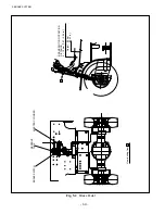
The parking brake lever is a toggle type and it is installed as shown in Fig. 5.9. An adjuster adjusting
the braking force is located on the top of the lever.
Parking brake alarm system
1. If the parking brake is released while the key switch
is in the OFF position:
Alarm
• The alarm buzzer keeps sounding regardless of
whether the operator is in the seat or not.
How to release the alarm
• Pull on the parking brake lever to set the brakes.
2. If the parking brake is released while the key switch
in the ON position:
Alarm
• The alarm buzzer will sound for one half second
if the parking brake is released and the operator
leaves the sat when the key switch is in the ON
position. If more than 3 seconds has passed after
the parking brake is released and the operator
leaves the seat, the alarm buzzer will keep
sounding.
How to release the alarm
• Sit down or pull on the parking brake lever to set
the brakes.
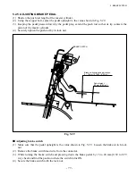
Adjusting brake switch
①
Loosen the two bolts securing the switch.
②
Pull the brake lever.
③
Press the switch roller against the arm. After it clicks, press another 1 mm [0.0394 in.] and lock.
④
Release the brake and pull the brake lever again to see if the switch is turned ON.
■
Adjusting lever pulling force
(1) Put the lever in the release position.
(2) Adjust the lever so that it is positioned as shown
in the
fi
gure when the point
B
of the lever is
pulled by a force of 29.4 to 49.0 N {3 to 5 kgf}
[21.7 to 36.1 lbf].
Turn the point
A
clockwise when you want a
harder pulling force and counterclockwise when
you want a lighter pulling force.
Fig. 5.9
Parking Brake Lever
PARKING
BRAKE LEVER
PARKING BRAKE SWITCH
RIGHT-SIDE CABLE
LEFT-SIDE CABLE
RELEASE
BUTTON
View looking from C
FITTING
BOLT
Fig. 5.10
FITTING BOLT
SWITCH
Содержание FB10-7
Страница 2: ......
Страница 4: ...No SEB 81BBE...
Страница 8: ...No SEB 81BBE...
Страница 9: ...No SEB 81BBE Fig 1 Overall Dimensions Unit mm in...
Страница 10: ...No SEB 81BBE...
Страница 28: ...1 BATTERY AND CHARGER 16 NOTE...
Страница 30: ...2 MOTORS 18 DRIVE UNIT Fig 2 1 Drive Motor Installation DRIVE AXLE DRIVE MOTOR...
Страница 42: ...3 CONTROL SYSTEM 30 Fig 3 2 Inverter Assembly 1 0 to 2 5 ton Trucks...
Страница 43: ...31 3 CONTROL SYSTEM Fig 3 3 Inverter Assembly 3 0 to 3 5 ton Trucks...
Страница 44: ...3 CONTROL SYSTEM 32 Fig 3 4 Controller Wiring 1 0 to 2 5 ton Trucks...
Страница 45: ...33 3 CONTROL SYSTEM Fig 3 5 Controller Wiring 3 0 to 3 5 ton Trucks...
Страница 133: ...7 HYDRAULIC SYSTEM 121 Fig 7 27 Remove the oil seal from the front cover...
Страница 160: ...8 LOAD HANDLING SYSTEM 148 NOTE...


