3. CONTROL SYSTEM
- 42 -
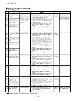
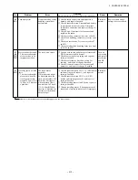
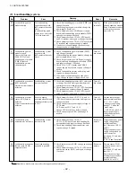
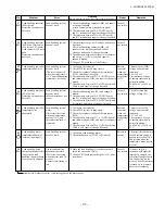
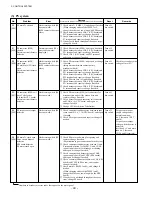
(2) Load handling system
No.
30
[403]
31
[404]
33
[406]
34
[402]
35
[401]
36
[504]
Problem
Load handling power
module shorted
Load handling power
module is open.
Upper side (between
P and OUT) of load
handling power module
(TMP) is shorted.
Load handling motor
shorted or open.
Load handling contactor
(MP) stuck open
Detection circuit harness
defective
Load handling current
sensor (CSP) output
defective
Circuit connector harness
defective
Load handling lift
potentiometer defective
Load handling controller
thermo sensor (THP)
output defective
Error
The load handling
system does not work.
(MP contactor does not
close.)
(Load handling quick
charge error: error code
70 is also detected.)
Load handling system
does not work.
(MP contactor does not
close.)
Load handling system
does not function.
Sensor is usually
activated when the load
handling continuity rate
is 30%.
Load handling system
does not work.
Usual load handling
operation is possible.
Remedy
Proceed with remedy in numerical order of encircled numbers.
①
Check load handling power module (TMP) and
change if needed.
When changing the power module, change the
power supply board, too.)
②
Check harness between CN4R (power supply
board) and load handling power module (TMP),
and repair or change if needed.
③
Check harness between CN4-10 (CPU board)
and P13 terminal, and repair or change if needed.
④
Check harness between CN4-8 (CPU board) and
P1 terminal, and repair or change if needed.
⑤
If no defect is found through the above steps,
change the power supply board.
①
Check load handling power module (TMP),
and change if needed.
(When changing the power module, change the
power supply board, too.)
②
Check harness between CN4R (power supply
board) and load handling power module (TMP),
and repair or change if needed.
③
Check CN8-3 (CPU board) and CN2R-3
(power supply board), and repair or change if
needed.
④
Check load handling motor and wiring, and
repair ore change if needed.
⑤
If no defect is found throughout the above
steps, change the power supply board, too.
①
Check load handling contactor (MP), and repair
or change if needed. (foreign matter between
contact points or mechanical hitch)
②
Check harness between CN5-22 (CPU board and
P11 terminal, and repair or change if needed.
③
Check harness between CN4-10 (CPU board)
and P13 terminal, and repair or change if needed.
①
Check harness between CN5-7, 8, 18, and 19
(CPU board) and current sensor, and repair or
change if needed.
②
Check current sensor power supply voltage of
CPU board.
CSP: between CN5-7 and 18, 19
Change CPU board if any defect is found.
③
Check current sensor (CSP), and change if
needed.
①
Check harness between CN2-5, 17,
CN11-10 (CPU board) and load handling lift
potentiometer, and repair or change if needed.
②
Check load handling lift potentiometer, and
repair or change if needed.
①
Check thermo sensor (THP) voltage, and change
if needed.
②
Check harness between CN7-6, 12 (CPU board)
and thermo sensor (THP), and repair or change
if needed.
Reset
Turn key
switch off.
Turn off
key switch.
Turn off
key switch.
Turn off
key switch.
Restore to
normal.
Restore to
normal.
Remarks
If the power module is
shorted, capacitor between
P and N terminals cannot
be charged to cause an
error code 70.
Current sensor output
under normal condition:
•
7 V - 9.35 V when
chopper is operating.
•
about 7 V when the
truck stops.
CSP: CN5-8 and 18, 19
Sensor power supply
voltage under normal
condition: 15 V
Lift potentiometer power
supply voltage under
normal condition:
4.6 V (between CN2-11
and 21)
Lift potentiometer power
supply voltage when an
error is detected:
less than 0.1 V and more
than 4.6 V
(CN2-10 and N terminal)
Thermo sensor (THP)
voltage when an error is
detected:
less than 0.2 V and more
than 4.95 V
The resistance/voltage
of thermo sensor under
normal condition:
20 k
Ω
/4.0 V at 25°C.
Numbers in brackets are error codes that appear on the meter panel.
Содержание FB10-7
Страница 2: ......
Страница 4: ...No SEB 81BBE...
Страница 8: ...No SEB 81BBE...
Страница 9: ...No SEB 81BBE Fig 1 Overall Dimensions Unit mm in...
Страница 10: ...No SEB 81BBE...
Страница 28: ...1 BATTERY AND CHARGER 16 NOTE...
Страница 30: ...2 MOTORS 18 DRIVE UNIT Fig 2 1 Drive Motor Installation DRIVE AXLE DRIVE MOTOR...
Страница 42: ...3 CONTROL SYSTEM 30 Fig 3 2 Inverter Assembly 1 0 to 2 5 ton Trucks...
Страница 43: ...31 3 CONTROL SYSTEM Fig 3 3 Inverter Assembly 3 0 to 3 5 ton Trucks...
Страница 44: ...3 CONTROL SYSTEM 32 Fig 3 4 Controller Wiring 1 0 to 2 5 ton Trucks...
Страница 45: ...33 3 CONTROL SYSTEM Fig 3 5 Controller Wiring 3 0 to 3 5 ton Trucks...
Страница 133: ...7 HYDRAULIC SYSTEM 121 Fig 7 27 Remove the oil seal from the front cover...
Страница 160: ...8 LOAD HANDLING SYSTEM 148 NOTE...

