1. BATTERY AND CHARGER
- 8 -
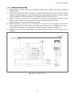
The VTM unit has two timers: One is called first timer and the other second timer. It is the first timer
on which the microprocessor sets the charging time (4 hours maximum).
The time to be set on the second timer is 15 hours for normal charging. If a single charging continues
longer than that duration, charging is treated as an abnormal termination. The lamp on the operation
panel then blinks and the display gives a message to inform the operator of that abnormal termination.
Data of past battery charge are stored in memory of the VTM unit. Based on these data, the
microcomputer judges whether or not the battery needs equalizing charge. The data store in memory
are:
* The changes in battery voltage and electrolyte temperature and voltage settings of charge sessions
performed within the last 40 hours
(94 hours for trucks manufactured earlier than January 31, 2004)
* The total charging hours, and the total hours during which the battery was connected to the charger.
* The number of times the battery got an equalizing charge.
* The number of times charging was terminated by the first timer.
* The number of times charging was terminated by the second timer.
* The number of times charging was stopped incomplete. (The number of times the stop button is
pressed.)
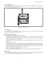
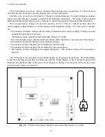
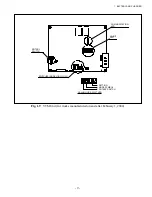
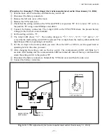
The VTM unit is also provided with an LED display on its printed circuit board. The LED display
is used for showing various data in connection with the charger/battery so that it helps the operator be
informed of adjustment data or the status of the charger according to the position of the setting switch
located on the printed circuit board.
Fig. 1.8
VTM Unit (for trucks manufactured earlier than January 31, 2004)
Содержание FB10-7
Страница 2: ......
Страница 4: ...No SEB 81BBE...
Страница 8: ...No SEB 81BBE...
Страница 9: ...No SEB 81BBE Fig 1 Overall Dimensions Unit mm in...
Страница 10: ...No SEB 81BBE...
Страница 28: ...1 BATTERY AND CHARGER 16 NOTE...
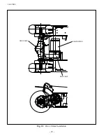
Страница 30: ...2 MOTORS 18 DRIVE UNIT Fig 2 1 Drive Motor Installation DRIVE AXLE DRIVE MOTOR...
Страница 42: ...3 CONTROL SYSTEM 30 Fig 3 2 Inverter Assembly 1 0 to 2 5 ton Trucks...
Страница 43: ...31 3 CONTROL SYSTEM Fig 3 3 Inverter Assembly 3 0 to 3 5 ton Trucks...
Страница 44: ...3 CONTROL SYSTEM 32 Fig 3 4 Controller Wiring 1 0 to 2 5 ton Trucks...
Страница 45: ...33 3 CONTROL SYSTEM Fig 3 5 Controller Wiring 3 0 to 3 5 ton Trucks...
Страница 133: ...7 HYDRAULIC SYSTEM 121 Fig 7 27 Remove the oil seal from the front cover...
Страница 160: ...8 LOAD HANDLING SYSTEM 148 NOTE...


