5. BRAKE SYSTEM
- 72 -
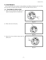
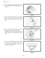
(4) Remove the primary and secondary shoes. Also
remove the adjuster and adjuster spring at the
same time.
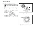
Fig. 5.16
Fig. 5.17
Fig. 5.18
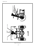
Fig. 5.19
(5) Remove the brake pipe from the wheel cylinder.
Remove the bolts securing the wheel cylinder.
Remove the wheel cylinder from the backing
plate.
(6) Remove the E retainer which secures the
parking brake cable to the backing plate.
After that, remove the bolt securing the backing
plate and remove the backing plate from the
axle.
(7) Remove the boot and insert the piston to remove
one of the two wheel cylinders. Then remove
the other wheel cylinder by pushing with a
finger from the opposite side.
Содержание FB10-7
Страница 2: ......
Страница 4: ...No SEB 81BBE...
Страница 8: ...No SEB 81BBE...
Страница 9: ...No SEB 81BBE Fig 1 Overall Dimensions Unit mm in...
Страница 10: ...No SEB 81BBE...
Страница 28: ...1 BATTERY AND CHARGER 16 NOTE...
Страница 30: ...2 MOTORS 18 DRIVE UNIT Fig 2 1 Drive Motor Installation DRIVE AXLE DRIVE MOTOR...
Страница 42: ...3 CONTROL SYSTEM 30 Fig 3 2 Inverter Assembly 1 0 to 2 5 ton Trucks...
Страница 43: ...31 3 CONTROL SYSTEM Fig 3 3 Inverter Assembly 3 0 to 3 5 ton Trucks...
Страница 44: ...3 CONTROL SYSTEM 32 Fig 3 4 Controller Wiring 1 0 to 2 5 ton Trucks...
Страница 45: ...33 3 CONTROL SYSTEM Fig 3 5 Controller Wiring 3 0 to 3 5 ton Trucks...
Страница 133: ...7 HYDRAULIC SYSTEM 121 Fig 7 27 Remove the oil seal from the front cover...
Страница 160: ...8 LOAD HANDLING SYSTEM 148 NOTE...


