5. BRAKE SYSTEM
- 76 -
5.2.4 OPERATION TEST OF AUTOMATIC CLEARANCE ADJUSTER
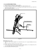
(1) Set the outer diameter of the brake shoe to nearly the normal mounting dimension. Push up the
adjuster lever and adjust the diameter, turning the teeth of the adjuster.
When your finger is released, the teeth of the adjuster do not turn and the adjuster lever returns to
the original position.
Note:
If the teeth of the adjuster return with the lever, they are adjusted properly after mounting the
brake system on the truck.
(2) If the operation described above does not occur by pushing up the adjuster lever, take the following
measures:
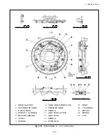
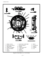
(a) Check that the adjuster lever, adjuster, adjuster sprint, adjuster cable and shoe return spring are
securely installed.
(b) Check the shoe return spring and adjuster spring for deterioration, the adjuster for rotation, damaged
tooth or damage of the contact area with the teeth of the adjuster lever, and replace any defective
parts.
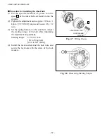
Fig. 5.28
Expanding part
Содержание FB10-7
Страница 2: ......
Страница 4: ...No SEB 81BBE...
Страница 8: ...No SEB 81BBE...
Страница 9: ...No SEB 81BBE Fig 1 Overall Dimensions Unit mm in...
Страница 10: ...No SEB 81BBE...
Страница 28: ...1 BATTERY AND CHARGER 16 NOTE...
Страница 30: ...2 MOTORS 18 DRIVE UNIT Fig 2 1 Drive Motor Installation DRIVE AXLE DRIVE MOTOR...
Страница 42: ...3 CONTROL SYSTEM 30 Fig 3 2 Inverter Assembly 1 0 to 2 5 ton Trucks...
Страница 43: ...31 3 CONTROL SYSTEM Fig 3 3 Inverter Assembly 3 0 to 3 5 ton Trucks...
Страница 44: ...3 CONTROL SYSTEM 32 Fig 3 4 Controller Wiring 1 0 to 2 5 ton Trucks...
Страница 45: ...33 3 CONTROL SYSTEM Fig 3 5 Controller Wiring 3 0 to 3 5 ton Trucks...
Страница 133: ...7 HYDRAULIC SYSTEM 121 Fig 7 27 Remove the oil seal from the front cover...
Страница 160: ...8 LOAD HANDLING SYSTEM 148 NOTE...

