1. BATTERY AND CHARGER
- 5 -
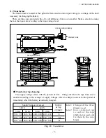
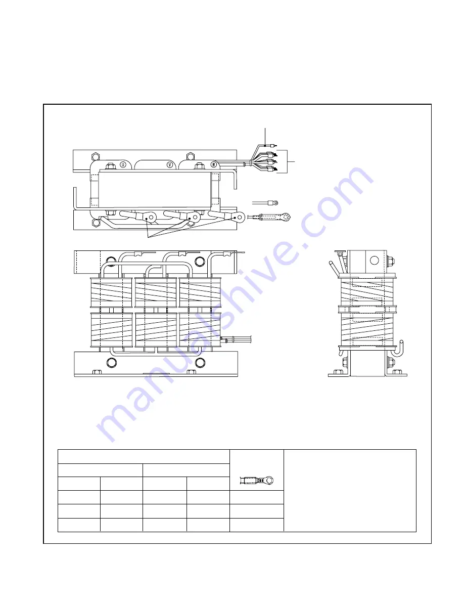
(1) Transformer
The transformer is located at the right side frame and converts input voltage to a voltage of the level
necessary for charging the battery.
There are three taps provided with a 10-volt difference from one to another. Make a selection among
them at the input side according to the input voltage level.
Fig. 1.5
Transformer
PRIMARY WIRE
■
Transformer tap changing
The supply voltage varies with the periods of time. Change therefore the taps from one to
another according to the average of supply voltages which to charger receives for the period of
time during which the battery is normally charged.
GROUND WIRE (GREEN)
SECONDARY WIRE
Supply Voltage (Average)
Symbol
380 V
440 V
of Tap
50 Hz
60 Hz
50 Hz
60 Hz
350 - 370 360 - 380 400 - 420 410 - 430
L
370 - 390 380 - 400 420 - 440 430 - 450
M
390 - 410 400 - 420 440 - 460 450 - 470
H
Note 1: Change all the three
phases as a set.
Note 2: Give a terminal cap
t o e a c h o f t h e t a p s
which are not used, and
fix them by the wire
binder.
Содержание FB10-7
Страница 2: ......
Страница 4: ...No SEB 81BBE...
Страница 8: ...No SEB 81BBE...
Страница 9: ...No SEB 81BBE Fig 1 Overall Dimensions Unit mm in...
Страница 10: ...No SEB 81BBE...
Страница 28: ...1 BATTERY AND CHARGER 16 NOTE...
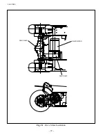
Страница 30: ...2 MOTORS 18 DRIVE UNIT Fig 2 1 Drive Motor Installation DRIVE AXLE DRIVE MOTOR...
Страница 42: ...3 CONTROL SYSTEM 30 Fig 3 2 Inverter Assembly 1 0 to 2 5 ton Trucks...
Страница 43: ...31 3 CONTROL SYSTEM Fig 3 3 Inverter Assembly 3 0 to 3 5 ton Trucks...
Страница 44: ...3 CONTROL SYSTEM 32 Fig 3 4 Controller Wiring 1 0 to 2 5 ton Trucks...
Страница 45: ...33 3 CONTROL SYSTEM Fig 3 5 Controller Wiring 3 0 to 3 5 ton Trucks...
Страница 133: ...7 HYDRAULIC SYSTEM 121 Fig 7 27 Remove the oil seal from the front cover...
Страница 160: ...8 LOAD HANDLING SYSTEM 148 NOTE...


