7. HYDRAULIC SYSTEM
- 123 -
⑥
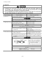
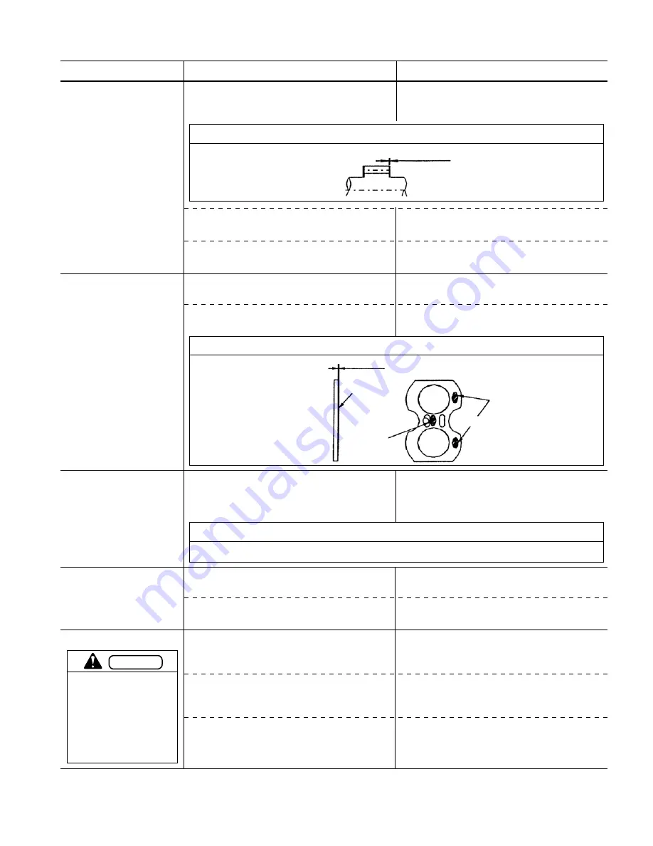
Gasket
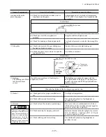
(a) Check gaskets for proper installation or
cut.
(b) Check rubber parts for swelling.
(a) Check oil seal for round or peeled edge.
(b) Check main lip for warping outward.
(c) Check rubber parts for swelling.
Name of component
Items to be checked
(c) Check for discoloration, undue wear, or
roughness on the gears.
Remarks (cause and others)
Contaminants in oil, too high oil temperature
(120
℃
[248
°
F] or higher), too frequently idle
operations
The oil seal might be
damaged when the drive
gear is disassembled or
when it is removed from
the front cover. It is diffi
-
cult to locate the cause of
damage when removing
it from the front cover.
(d) Check gear teeth for roughness or
pitching.
(e) Check for missing or broken gear teeth
(a) Check side plate in the gear sliding area
for wear or nicks or scores.
(b) Check the gears for erosion at or near the
engagement area.
Irregular rotation at high speeds
Too high oil pressure or a hard object caught in
gear
Fine dust between side plate and gears
Cavitation or aeration
Useful limit
0.1 mm [0.0040 in] or less
④
Side plate
Useful limit
These areas
might be worn
Wear limit: 0.15 mm (0.006 in) or less
LBC surface
Discharge port
Erosion
might occur
here due to
cavitation.
Suction port
⑤
Bushing
The bushings are fitted
into front and rear
covers.
Check the inner surfaces of bushings for
roughness or wear.
The bushings are made of copper with the
back plate made of lead brass. The back plate
consists of porous and PTFE (polytetrafluoro-
ethylene) layers.
Useful limit
When the back plate of the bushing is exposed to view.
Too high oil temperature
Fire retardant hydraulic oil (phosphate) or
gasoline is used.
Wear occurs due to contaminants in oil, dust
which enters oil due to undue external negative
pressure, or rust due to moisture.
Increased internal oil leaks or high oil pressure
(0.2 - 0.3 MPa {2 - 3 kgf/cm
2
} [28.5 - 42.7 psi]
or more) applied on oil seal
Fire retardant hydraulic oil (phosphate) or
gasoline is used.
⑦
Oil seal
CAUTION
(continued from the
preceding page)
Содержание FB10-7
Страница 2: ......
Страница 4: ...No SEB 81BBE...
Страница 8: ...No SEB 81BBE...
Страница 9: ...No SEB 81BBE Fig 1 Overall Dimensions Unit mm in...
Страница 10: ...No SEB 81BBE...
Страница 28: ...1 BATTERY AND CHARGER 16 NOTE...
Страница 30: ...2 MOTORS 18 DRIVE UNIT Fig 2 1 Drive Motor Installation DRIVE AXLE DRIVE MOTOR...
Страница 42: ...3 CONTROL SYSTEM 30 Fig 3 2 Inverter Assembly 1 0 to 2 5 ton Trucks...
Страница 43: ...31 3 CONTROL SYSTEM Fig 3 3 Inverter Assembly 3 0 to 3 5 ton Trucks...
Страница 44: ...3 CONTROL SYSTEM 32 Fig 3 4 Controller Wiring 1 0 to 2 5 ton Trucks...
Страница 45: ...33 3 CONTROL SYSTEM Fig 3 5 Controller Wiring 3 0 to 3 5 ton Trucks...
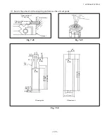
Страница 133: ...7 HYDRAULIC SYSTEM 121 Fig 7 27 Remove the oil seal from the front cover...
Страница 160: ...8 LOAD HANDLING SYSTEM 148 NOTE...


