4. DRIVE UNIT AND DRIVE AXLE
- 62 -
■
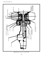
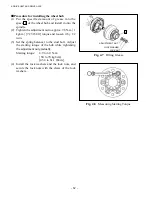
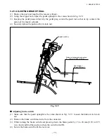
Procedure for installing the wheel hub
(1) Put the specified amount of grease into the
space
A
of the wheel hub and install it onto the
spindle.
(2) Tighten the adjustment nut to approx. 98 N-m {1
kgf-m} [7.23 lbf-ft] torque and loosen it by 1/2
turn.
(3) Set the spring balancer to the stud bolt. Adjust
the starting torque of the hub while tightening
the adjustment nut gradually.
Starting torque: 4.9 to 6.9 N-m
{50 to 70 kgf-cm}
[43.4 to 61.1 lbf-in.]
(4) Install the lock washers and the lock nuts, and
secure the lock nuts with the claws of the lock
washers.
LOCK NUT
Fig. 4.7
Filling Grease
Fig. 4.8
Measuring Starting Torque
ADJUSTMENT NUT
LOCK WASHER
A
Содержание FB10-7
Страница 2: ......
Страница 4: ...No SEB 81BBE...
Страница 8: ...No SEB 81BBE...
Страница 9: ...No SEB 81BBE Fig 1 Overall Dimensions Unit mm in...
Страница 10: ...No SEB 81BBE...
Страница 28: ...1 BATTERY AND CHARGER 16 NOTE...
Страница 30: ...2 MOTORS 18 DRIVE UNIT Fig 2 1 Drive Motor Installation DRIVE AXLE DRIVE MOTOR...
Страница 42: ...3 CONTROL SYSTEM 30 Fig 3 2 Inverter Assembly 1 0 to 2 5 ton Trucks...
Страница 43: ...31 3 CONTROL SYSTEM Fig 3 3 Inverter Assembly 3 0 to 3 5 ton Trucks...
Страница 44: ...3 CONTROL SYSTEM 32 Fig 3 4 Controller Wiring 1 0 to 2 5 ton Trucks...
Страница 45: ...33 3 CONTROL SYSTEM Fig 3 5 Controller Wiring 3 0 to 3 5 ton Trucks...
Страница 133: ...7 HYDRAULIC SYSTEM 121 Fig 7 27 Remove the oil seal from the front cover...
Страница 160: ...8 LOAD HANDLING SYSTEM 148 NOTE...


