4. DRIVE UNIT AND DRIVE AXLE
- 55 -
4. DRIVE UNIT AND DRIVE AXLE
Truck model
FB10-7 FB15-7
FB20-7 FB25-7
FB30-7
FB18-7
FB25-7LB FB25-7V
FB30-7V
Item
FB35-7S
Drive unit
Type
Three-stage reduction
←
←
Model
81E-25
81N-25
81U-25
Reduction ratio
25.1
←
30.144
Drive axle
Type
Full
fl
oating
←
←
Wheel dimensions
6.00 x 9 – 10PR Rib lug 21 x 8 – 9 16PR Rib lug 28 x 9 – 15 14PR Rib lug
FB18: 6.00x9-12PR Rib lug
FB35: 250-15-16PR J lug
Rim size
9 x 4.00E
9 x 6.00E
7.00T x 15
Air pressure
850 kPa {8.5 kgf/cm
2
} 1000 kPa {10 kgf/cm
2
} 800 kPa {8.0 kgf/cm
2
}
[120.9 psi]
[142.2 psi]
[100 psi]
FB18: 1000 kPa
{10
kgf/cm
2
} [142.2 psi]
4.1 GENERAL DESCRIPTION
4.1.1 DRIVE UNIT
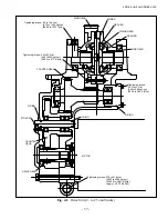
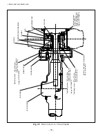
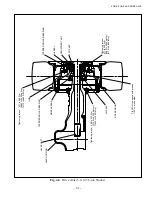
The drive unit is a three-stage reduction type and located between the drive motor and the drive axle
as shown in Figs. 4.1 through 4.3.
The drive gear is splined to the output shaft of the drive motor, being in mesh with the counter
gear. The drive gear is supported by two ball bearings on the case. The rotation of the drive gear is
transmitted to the
fi
nal pinion gear.
In the case the differential is installed by two ball bearings. The cross case has two side gears and
four pinions in it (Two pinions for the model 81E-25). For adjustment of the backlash between each
side gear and pinion, a washer is installed. These washers also work as bearings.
To the cross case a ring gear is
fi
tted by a reamer bolt. The ring is in mesh with the
fi
nal pinion gear.
Содержание FB10-7
Страница 2: ......
Страница 4: ...No SEB 81BBE...
Страница 8: ...No SEB 81BBE...
Страница 9: ...No SEB 81BBE Fig 1 Overall Dimensions Unit mm in...
Страница 10: ...No SEB 81BBE...
Страница 28: ...1 BATTERY AND CHARGER 16 NOTE...
Страница 30: ...2 MOTORS 18 DRIVE UNIT Fig 2 1 Drive Motor Installation DRIVE AXLE DRIVE MOTOR...
Страница 42: ...3 CONTROL SYSTEM 30 Fig 3 2 Inverter Assembly 1 0 to 2 5 ton Trucks...
Страница 43: ...31 3 CONTROL SYSTEM Fig 3 3 Inverter Assembly 3 0 to 3 5 ton Trucks...
Страница 44: ...3 CONTROL SYSTEM 32 Fig 3 4 Controller Wiring 1 0 to 2 5 ton Trucks...
Страница 45: ...33 3 CONTROL SYSTEM Fig 3 5 Controller Wiring 3 0 to 3 5 ton Trucks...
Страница 133: ...7 HYDRAULIC SYSTEM 121 Fig 7 27 Remove the oil seal from the front cover...
Страница 160: ...8 LOAD HANDLING SYSTEM 148 NOTE...

