2. MOTORS
- 27 -
2.2.2 PUMP MOTOR
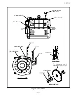
(1) Ball bearing
In case when the ball bearing gives out abnormal noise or seizes up, remove it from the armature
shaft.
For removing the ball bearing, apply a force to the outer race of the bearing by using a small-sized
puller. Do not use the bearing once removed.
For installing a new bearing, apply a force to the inner race of the bearing by using a cylinder-shaped
jig.
(2) Measurement of insulation resistance
Connect the negative (-) terminal of a meter to the motor yoke, and the positive (+) terminal to either
one of the two lead wires. Then measure the resistance. It is normal when the pointer of the meter
indicates higher than 1 M
Ω
.
If the meter reads than 1 M
Ω
, remove carbon deposit from inside the motor by blowing air, and dry it
by a dryer if available. Then measure the resistance again.
If the resistance measured again is lower than 1 M
Ω
replace the motor with a new one.
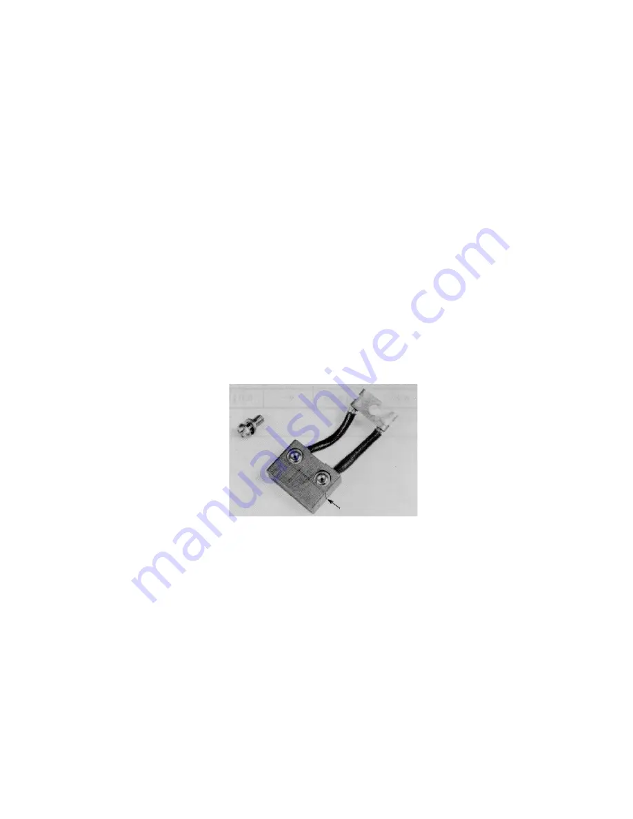
(3) Brush and brush spring checking
The brush has a marking on it to indicate wear limit. When the brush is worn to that limit, replace.
For measuring the tension of the brush spring that pushes the brush against the commutator, use a
spring balance.
Fig. 2.10
MARKING
Содержание FB10-7
Страница 2: ......
Страница 4: ...No SEB 81BBE...
Страница 8: ...No SEB 81BBE...
Страница 9: ...No SEB 81BBE Fig 1 Overall Dimensions Unit mm in...
Страница 10: ...No SEB 81BBE...
Страница 28: ...1 BATTERY AND CHARGER 16 NOTE...
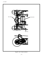
Страница 30: ...2 MOTORS 18 DRIVE UNIT Fig 2 1 Drive Motor Installation DRIVE AXLE DRIVE MOTOR...
Страница 42: ...3 CONTROL SYSTEM 30 Fig 3 2 Inverter Assembly 1 0 to 2 5 ton Trucks...
Страница 43: ...31 3 CONTROL SYSTEM Fig 3 3 Inverter Assembly 3 0 to 3 5 ton Trucks...
Страница 44: ...3 CONTROL SYSTEM 32 Fig 3 4 Controller Wiring 1 0 to 2 5 ton Trucks...
Страница 45: ...33 3 CONTROL SYSTEM Fig 3 5 Controller Wiring 3 0 to 3 5 ton Trucks...
Страница 133: ...7 HYDRAULIC SYSTEM 121 Fig 7 27 Remove the oil seal from the front cover...
Страница 160: ...8 LOAD HANDLING SYSTEM 148 NOTE...


