2. MOTORS
- 20 -
■
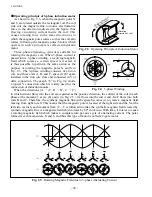
Operating principle of 3-phase induction motor
As shown in Fig. 2.3, when the magnetic poles N
and S are rotated outside the rectangular oil, the coil
side cuts the magnetic flux to induce electromotive
force in the direction indicated in the figure, thus
flowing circulating current inside the coil. This
causes rotating force in the same direction as in
which the magnetic poles rotates so that the coil also
rotates, following the magnetic poles. Motors which
operate in such a principle is called an induction
motor.
Three-phase alternating current is suitable for
rotating the magnetic coil. When 3-phase current is
passed into a 3-phase winding, a revolving magnetic
field which rotates a certain speed is created. It
is thus possible to perform the same action as the
purpose of rotating the magnetic poles N and S in
Fig. 2.3. The 3-phase winding consists of an iron
core and three coils A, B, and C, spaced 120° apart,
installed in the iron core slots and connected in Y or
delta connection. The sketch “b” in Fig. 2.4 shows
a typical Y connection which is widely used for the
connection of induction motors.
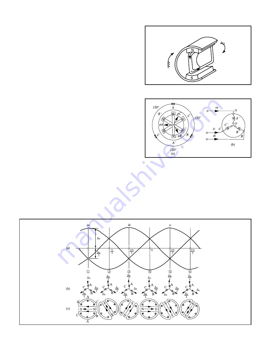
When the directions (A
→
A’, B
→
B’, C
→
C’)
in which current flows into the coil are regarded as the positive direction, the current of the coil in each
phase at the moment
①
at (a), (b) and (c) in Fig. 2.5, +
I
m flows into the coil A and –
I
m/2 flows into both
coils B and C. Therefore, the synthetic magnetic flux in the space becomes (c) to create a magnetic field
moving from right to left. This means that the magnetic pole is located at the right side and the S at the
left side. As such, each moment from
②
-
⑥
is followed in order, the synthetic magnetic field created by
synthetic magnetic flux is a magnetic field which rotates by 60° clockwise. With time, it rotates to cause
a rotating magnetic field which makes a complete turn per one cycle of alternating current. The poles
formed at each moment are N and S, and thus this type of motor is called a 2-pole motor.
Fig. 2.3
Operating Principle of Induction Motor
Fig. 2.4
3-phase Winding
(Rotating
direction of coil)
(Rotating direction
of magnetic pole)
Fig. 2.5
Rotating Magnetic Field due to 3-phase Alternating Current
Содержание FB10-7
Страница 2: ......
Страница 4: ...No SEB 81BBE...
Страница 8: ...No SEB 81BBE...
Страница 9: ...No SEB 81BBE Fig 1 Overall Dimensions Unit mm in...
Страница 10: ...No SEB 81BBE...
Страница 28: ...1 BATTERY AND CHARGER 16 NOTE...
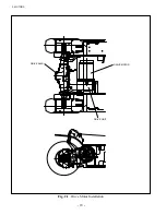
Страница 30: ...2 MOTORS 18 DRIVE UNIT Fig 2 1 Drive Motor Installation DRIVE AXLE DRIVE MOTOR...
Страница 42: ...3 CONTROL SYSTEM 30 Fig 3 2 Inverter Assembly 1 0 to 2 5 ton Trucks...
Страница 43: ...31 3 CONTROL SYSTEM Fig 3 3 Inverter Assembly 3 0 to 3 5 ton Trucks...
Страница 44: ...3 CONTROL SYSTEM 32 Fig 3 4 Controller Wiring 1 0 to 2 5 ton Trucks...
Страница 45: ...33 3 CONTROL SYSTEM Fig 3 5 Controller Wiring 3 0 to 3 5 ton Trucks...
Страница 133: ...7 HYDRAULIC SYSTEM 121 Fig 7 27 Remove the oil seal from the front cover...
Страница 160: ...8 LOAD HANDLING SYSTEM 148 NOTE...


