7. HYDRAULIC SYSTEM
- 108 -
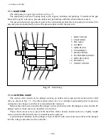
7.1.3 HYDRAULIC OIL TANK
The hydraulic oil tank is located at the center of the frame. In the tank, a suction filter and a return
filter are provided for the purpose of ensuring clean oil supply.
(1) Replacing filters
①
Remove the drain plug and drain the oil tank.
②
Clean the tank cover surrounding area. Then remove the cover securing bolts.
③
Remove the suction and return hoses.
④
Remove the tank cover.
⑤
Remove the return filter, then install a new return filter.
⑥
Remove the suction filter, then install a new suction filter.
⑦
Remove the packings from the cover and the tank, then apply sealing agent to the tank.
Sealing agent: THREEBOND#4001 or equivalent
⑧
Reinstall the tank cover, then connect the suction and return hoses.
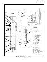
DRAIN PLUG
Fig. 7.5
Hydraulic Oil Tank
OIL FILL CAP
(w/ OIL DIPSTICK)
BREATHER
RETURN FILTER
SUCTION FILTER
FB10 - 18: 18L
FB20 - 35: 25L
Содержание FB10-7
Страница 2: ......
Страница 4: ...No SEB 81BBE...
Страница 8: ...No SEB 81BBE...
Страница 9: ...No SEB 81BBE Fig 1 Overall Dimensions Unit mm in...
Страница 10: ...No SEB 81BBE...
Страница 28: ...1 BATTERY AND CHARGER 16 NOTE...
Страница 30: ...2 MOTORS 18 DRIVE UNIT Fig 2 1 Drive Motor Installation DRIVE AXLE DRIVE MOTOR...
Страница 42: ...3 CONTROL SYSTEM 30 Fig 3 2 Inverter Assembly 1 0 to 2 5 ton Trucks...
Страница 43: ...31 3 CONTROL SYSTEM Fig 3 3 Inverter Assembly 3 0 to 3 5 ton Trucks...
Страница 44: ...3 CONTROL SYSTEM 32 Fig 3 4 Controller Wiring 1 0 to 2 5 ton Trucks...
Страница 45: ...33 3 CONTROL SYSTEM Fig 3 5 Controller Wiring 3 0 to 3 5 ton Trucks...
Страница 133: ...7 HYDRAULIC SYSTEM 121 Fig 7 27 Remove the oil seal from the front cover...
Страница 160: ...8 LOAD HANDLING SYSTEM 148 NOTE...

