6. STEERING SYSTEM
- 97 -
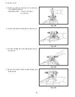
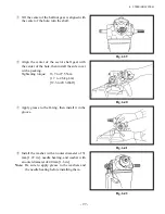
Fig. 6.39
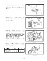
Fig. 6.40
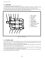
Fig. 6.41
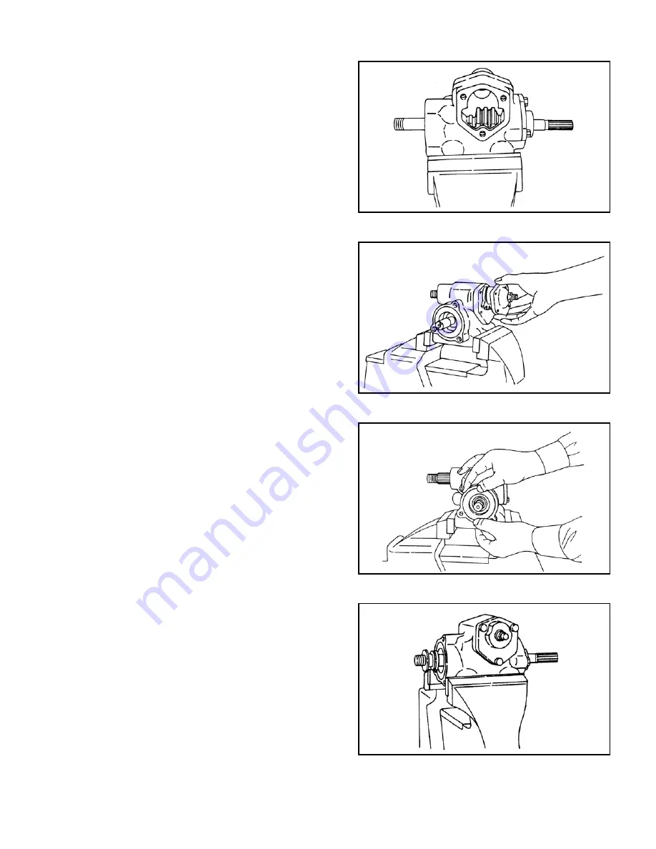
Fig. 6.42
⑤
Till the center of the ball nut gear is aligned with
the center of the hole, turn the shaft.
⑥
Align the center of the sector shaft gear with
the center of the hole, then install the side cover
with a packing.
Tightening torque: 16.7 to 27.5 N-m
{1.7 to 2.8 kgf-m}
[12.3 to 20.3 lbf-ft]
⑦
Apply grease to the O-ring, then install it in the
groove.
⑧
Install the washer with an outer diameter of 31
mm [1.22 in.], needle bearing, and washer with
an outer diameter of 40 mm [1.6 in.].
Note:
Be sure to apply grease to the washers and
the needle bearing before installing them.
Содержание FB10-7
Страница 2: ......
Страница 4: ...No SEB 81BBE...
Страница 8: ...No SEB 81BBE...
Страница 9: ...No SEB 81BBE Fig 1 Overall Dimensions Unit mm in...
Страница 10: ...No SEB 81BBE...
Страница 28: ...1 BATTERY AND CHARGER 16 NOTE...
Страница 30: ...2 MOTORS 18 DRIVE UNIT Fig 2 1 Drive Motor Installation DRIVE AXLE DRIVE MOTOR...
Страница 42: ...3 CONTROL SYSTEM 30 Fig 3 2 Inverter Assembly 1 0 to 2 5 ton Trucks...
Страница 43: ...31 3 CONTROL SYSTEM Fig 3 3 Inverter Assembly 3 0 to 3 5 ton Trucks...
Страница 44: ...3 CONTROL SYSTEM 32 Fig 3 4 Controller Wiring 1 0 to 2 5 ton Trucks...
Страница 45: ...33 3 CONTROL SYSTEM Fig 3 5 Controller Wiring 3 0 to 3 5 ton Trucks...
Страница 133: ...7 HYDRAULIC SYSTEM 121 Fig 7 27 Remove the oil seal from the front cover...
Страница 160: ...8 LOAD HANDLING SYSTEM 148 NOTE...


