- 45 -
3. CONTROL SYSTEM
■
Inspecting controller components
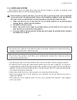
Do not touch any electrical component with the truck in conduction. When it is necessary to touch
an electrical component for any reason, such as inspection or maintenance, disconnect the battery
connectors and wait for more than 2 minutes before starting the operation.
If avoidable to inspect an energized truck, raise the drive wheels off the floor or ground to prevent the
truck from moving accidentally when the motor suddenly starts rotating for any reason.
In addition, use caution to prevent your body from touching the tires.
1. Checking electrical components of controller
(1) Tools and measuring equipment
(2) Tightening torque
No.
Name
Spec. & remarks
Use
Phillips and flat-bladed screwdrivers (large, medium,
Tighten and remove screws.
1 Screwdriver set
and small, one for each), flat-bladed screwdriver for
Set adjustment control.
small screws
2 Wrench set
7 mm, 13 mm, 17 mm
Tighten and remove bolts and nuts
(socket wrenches)
3 Torque wrench
Power module fitting screws: M4, M5
Measure tightening torque of power modules
4 Tweezers and pliers
Install and remove small parts
5 Ammeter
DC500A or 1000A
Measure electric current
6 Digital tester
up to 12 V, 30 V, 120 V
Measure voltage
Analog tester
range: x 1
Ω
, x 100
Ω
, x 1000
Ω
Measure resistance (digital tester cannot be used for this purpose.)
7 Oscilloscope
Check transistor circuit
8 Stabilized power
0 - 50 V, variable, 3A conductable
Check operation of each component.
supply for control
Where to tighten
Symbol
Truck
Model
Screw Torque
Remarks
Part name
Item
size
(N-m)
Printed circuit
Fixed
1 t
N61F30851=3
M4.5 1.0
board (CPU)
2 t
N61F30851=4
3 t, 3.5 t N61F30851=5
Printed circuit board
Fixed
Common N61F30841=7
M4.5 1.0
(power supply)
Power module
Fixed
TMDU
1 t
N51F45956=222
M5
2.5 ± 0.5 Heat-dissipation, insulation
TMDV/W
N51F45481=222
sheet is placed on the base.
TMP
N51F45956=216
For shape, see *1.
TMDU
2 t
N51F46529=224
TMDV/W
N51F46528=224
TMP
N51F45956=216
TMDU
3 t
N51F46529=124
TMDV/W
3.5 t
N51F46528=124
TMP
N51F45956=114
Power module
Fixed
Common N55F42549
M5
2.5 ± 0.5
Alminum block terminal Terminal
M8
9.8 ± 1
Capacitor board
Fixed & terminal CBD
1 t
N61F30830=221
M5
2.5 ± 0.5 M4 screw is used for two
CBP
N61F30831=215
M4
1.5 ± 0.2 studs of CBP.
CBD
2 t
N61F30813=230
CBP
N61F30831=215
CBD
3 t
N61F30813=150
CBP
3.5 t
N61F30831=114
Contactor
Fixed
MD
1 t, 3 t,
MA25M 46V
M5
2.5 ± 0.5
Terminal
MP
3.5 t
MA25M 46V
M8
9.8 ± 1
Fixed
MD
2 t
MA27M 46V
M5
2.5 ± 0.5
Terminal
MP
MA25M 46V
M8
9.8 ± 1
Contactor
Fixed
MPS
Common CM2-A DC48V
M4
1.5 ± 0.2
Terminal
M4
1.3 ± 0.2
Current sensor
Fixed
CSDU/W, CSP
Common S3CM7-800/4MD
M4
1.5 ± 0.2
IGBT
Fixed
TMPS1/2
Common 2MBI100N-60
M5
2.5 ± 0.5
Terminal
M5
2.5 ± 0.5
Capacitor CP5
Fixed
CPS
Common N71F41314
M4
1.5 ± 0.2 HFC-MPP63Y155K
+0.5
0
+0.5
0
Содержание FB10-7
Страница 2: ......
Страница 4: ...No SEB 81BBE...
Страница 8: ...No SEB 81BBE...
Страница 9: ...No SEB 81BBE Fig 1 Overall Dimensions Unit mm in...
Страница 10: ...No SEB 81BBE...
Страница 28: ...1 BATTERY AND CHARGER 16 NOTE...
Страница 30: ...2 MOTORS 18 DRIVE UNIT Fig 2 1 Drive Motor Installation DRIVE AXLE DRIVE MOTOR...
Страница 42: ...3 CONTROL SYSTEM 30 Fig 3 2 Inverter Assembly 1 0 to 2 5 ton Trucks...
Страница 43: ...31 3 CONTROL SYSTEM Fig 3 3 Inverter Assembly 3 0 to 3 5 ton Trucks...
Страница 44: ...3 CONTROL SYSTEM 32 Fig 3 4 Controller Wiring 1 0 to 2 5 ton Trucks...
Страница 45: ...33 3 CONTROL SYSTEM Fig 3 5 Controller Wiring 3 0 to 3 5 ton Trucks...
Страница 133: ...7 HYDRAULIC SYSTEM 121 Fig 7 27 Remove the oil seal from the front cover...
Страница 160: ...8 LOAD HANDLING SYSTEM 148 NOTE...


