7. HYDRAULIC SYSTEM
- 103 -
7. HYDRAULIC SYSTEM
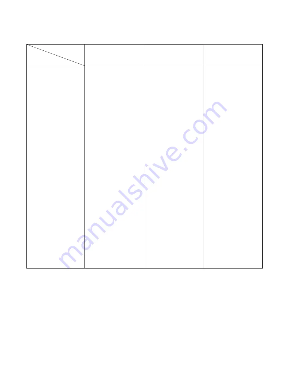
Truck model
Item
FB10-7 FB15-7
FB18-7
FB20-7
FB25-7
FB25-7LB FB25-7V
FB30-7
FB30-7V
FB35-7S
Main pump
Type
Name
Discharge
Drive
Control valve
Type
Name
Pressure setting
Lift cylinder
Type
Cylinder inner dia.
Rod outer dia.
Stroke
Tilt cylinder
Type
Cylinder inner dia.
Rod outer dia.
Stroke
Hydraulic oil tank
Capacity
Gear type
TMG1A18
18.9 c.c./rev
Directly connected to
motor
Spool sliding type
MSV04
14.2 MPa
{145 kgf/cm
2
} [2062 psi]
FB18: 15.7MPa
{160 kgf/cm
2
} [2275 psi]
Single-acting piston type
45 mm [1.77 in.]
35 mm [1.38 in.]
1495 mm [57.4 in.]
(when lifting height is
3000 mm [118.1 in.])
Double-acting piston type
65 mm [2.56 in.]
30 mm [1.2 in.]
120 mm [4.72 in.]
18 L [4.8 US gal]
←
TMG1A20
21 c.c./rev
←
←
←
17.2 MPa
{175 kgf/cm
2
} [2489 psi]
←
50 mm [1.97 in.]
40 mm [1.58 in.]
←
←
70 mm [2.8 in.]
←
139 mm [5.47 in.]
25 L [6.6 US gal]
←
TMG1A23
24.5 c.c./rev
←
←
←
←
←
55 mm [2.17 in.]
FB35: 60 mm [2.36 in.]
45 mm [1.77 in.]
FB35: 50 mm [1.97 in.]
←
←
←
FB35: 90 mm [3.54 in.]
←
FB35: 45 mm [1.77 in.]
151 mm [5.94 in.]
FB35: 137 mm [5.4 in.]
←
7.1 GENERAL DESCRIPTION
The hydraulic system consists of a pump, control valve, tank, lift cylinders, and tilt cylinders.
Oil is supplied by the pump directly driven by a motor. The control valve is used for controlling
cylinders.
For the high-pressure piping, the O-ring fitting method that provides high sealing performance is
employed to improve hydraulic system serviceability.
For lifting operation, the load handling DC chopper is used to control motor operation so as to
achieve the lifting speed that complies with the amount of lever operation.
Содержание FB10-7
Страница 2: ......
Страница 4: ...No SEB 81BBE...
Страница 8: ...No SEB 81BBE...
Страница 9: ...No SEB 81BBE Fig 1 Overall Dimensions Unit mm in...
Страница 10: ...No SEB 81BBE...
Страница 28: ...1 BATTERY AND CHARGER 16 NOTE...
Страница 30: ...2 MOTORS 18 DRIVE UNIT Fig 2 1 Drive Motor Installation DRIVE AXLE DRIVE MOTOR...
Страница 42: ...3 CONTROL SYSTEM 30 Fig 3 2 Inverter Assembly 1 0 to 2 5 ton Trucks...
Страница 43: ...31 3 CONTROL SYSTEM Fig 3 3 Inverter Assembly 3 0 to 3 5 ton Trucks...
Страница 44: ...3 CONTROL SYSTEM 32 Fig 3 4 Controller Wiring 1 0 to 2 5 ton Trucks...
Страница 45: ...33 3 CONTROL SYSTEM Fig 3 5 Controller Wiring 3 0 to 3 5 ton Trucks...
Страница 133: ...7 HYDRAULIC SYSTEM 121 Fig 7 27 Remove the oil seal from the front cover...
Страница 160: ...8 LOAD HANDLING SYSTEM 148 NOTE...


