


24
2. "Loudspeaker Mute Setting”
Mute/Not mute loudspeaker of congress units (except
interpreter units).
a). Press the “
Õ
/
Ö
” button to select mute or not;
b). Press the “MENU” button to save and return to the
upper level menu.
3. “LINE IN 1 Mode Setting”
Select LINE IN 1 mode from “Line input” or
“Microphone Input”.
a). Press the “
Õ
/
Ö
” button to select “Line Input” or
“Microphone Input”;
Select “Line Input” and press the “MENU” button
to save and return to the upper level menu;
Select “Microphone Input” and press the
“MENU” button will go to step b);
b). Press the “
Õ
/
Ö
” button to select phantom power
on/off, phantom power is used for connecting
condenser microphone;
c). Press the “MENU” button to save and return to the
upper level menu.
4. “Line Out 2 Mode Setting”
Set up Line Out 2 microphone output mode.
a). Press the “
Õ
/
Ö
” button to select “On” or “Off”;
Select “On” stands Line Out 2 will output mixed
microphone signals only;
Select “Off” stands Line Out 2 will output mixed
audio of microphone signals, Line In 1 signal and
Line In 2 signal;
b). Press the “MENU” button to save and return to the
upper level menu.
5. “Down Bass Setting”
Adjust downlink bass of congress units (except
interpreter units), range: -15dB - +15 dB.
a). Press the “
Õ
/
Ö
” button to adjust;
b). Press the “MENU” button to save and return to the
upper level menu.
6. “Down Treble Setting”
Adjust downlink treble of congress units (except
interpreter units), range: -15dB - +15 dB.
a). Press the “
Õ
/
Ö
” button to adjust;
b). Press the “MENU” button to save and return to the
upper level menu.
7. “Down Threshold Level Setting”
Setup downlink audio threshold level to make sure that
the sound issuing from the built-in loudspeaker and the
headphone of each congress unit has no distortion.
a). Press the “
Õ
/
Ö
” button to select threshold level
between -21dB, -18dB and -15dB;
b). Press the “MENU” button to save and return to the
upper level menu.
Note:
)
“Down” and “downlink” used in 5./6. and 7. indicate
the signal transmission direction from the main unit
to the congress units.
Содержание HCS-4100/50 Series
Страница 46: ...33 Figure 2 10 Floor mode setting Normal Mode Figure 2 11 Floor mode setting Insert Mode...
Страница 47: ...34 Figure 2 12 Floor mode setting Sync Line Out1 Mixer...
Страница 58: ...45 3 2 2 Installation 3 2 2 1 Cutout Figure 3 3 Cutout of HCS 48U7 series flush mounted congress unit unit mm...
Страница 59: ...46 Figure 3 4 Cutout of HCS 48U8 series flush mounted congress unit unit mm...
Страница 60: ...47 Figure 3 5 Cutout of HCS 48U9 series flush mounted congress unit unit mm except HCS 48U9DFFF...
Страница 61: ...48 Figure 3 6 Cutout of HCS 48U9DFFF flush mounted congress unit unit mm...
Страница 62: ...49 3 2 2 2 Installation Figure 3 7 Installation of HCS 48U7 series flush mounted congress unit...
Страница 63: ...50 Figure 3 8 Installation of HCS 48U8 series and HCS 48U9 series flush mounted congress unit...
Страница 65: ...52 Figure 3 11 Disassembly caution of HCS 48U8 and HCS 48U9 series flush mounted congress unit...
Страница 130: ...117 Figure 3 43 Installation of HCS 4325U 50 congress unit unit mm...
Страница 143: ...130 Figure 3 57 Multi function connector connected to the HCS 4341 50 series congress unit...
Страница 155: ...141 Figure 3 72 Multi function connector connected to HCS 4841 42 43 series congress units...
Страница 168: ...154 3 12 3 Connection Figure 3 83 Connection of HCS 1030U Electronic Nameplate with HCS 48U8 series congress unit...
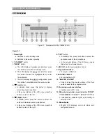
Страница 170: ...156 4 1 Functions and indications Front Side Bottom Figure 4 1 HCS 4385U 50 Interpreter unit...
Страница 223: ...www taiden com TAIDEN INDUSTRIAL CO LTD Copyright by TAIDEN Last Revision 06 2013...