


SSI700 User Manual Operation, Display and Application Example
www.ssinverter.info
disappears and the operation panel returns to the normal parameter display status, it
indicates that the auto-tuning is complete.
The AC drive will automatically calculate the following motor parameters:
P1-06: Stator resistance (asynchronous motor)
P1-07: Rotor resistance (asynchronous motor)
P1-08: Leakage inductive reactance (asynchronous motor)
P1-09: Mutual inductive reactance (asynchronous motor)
P1-10: No-load current (asynchronous motor)
If the motor cannot be disconnected from the load, set P1-11 (Auto-tuning selection) to 1
(Asynchronous motor static tuning) and then press on the operation panel. The
motor auto-tuning starts.
4.7.3 Setting and Switchover of Multiple Groups of Motor Parameters
You can select the current effective motor parameter group by means of function code
P0-26 or DI terminals with functions 41 and 42. When the DI terminals with functions 41
and 42 become ON, they are privileged and the setting of P0-26 becomes invalid.
4.8 Use of DI Terminals
The control board provides five DI terminals DI1 to DI5.
The internal hardware of DI terminals are configured with 24 VDC power supply for
detection. You can input a signal to a DI terminal of the AC drive only by shorting the DI
terminal and COM.
By default, P4-38 = 0000 and P4-39 = 0000. When a DI terminal is shorted to COM, it
isactive (logic 1). When a DI terminal is not shorted to COM, it is inactive (logic 0).
You can change the DI terminal active mode. That is, a DI terminal is inactive (logic 0)
when being shorted with COM, and active (logic 1) when being not shorted to COM. In
this case, it is necessary to change the corresponding bit in P4-38 and P4-39 (these two
parameters respectively specifying the active mode setting of DI1 to DI5 and DI16 to
DI10) to 1.
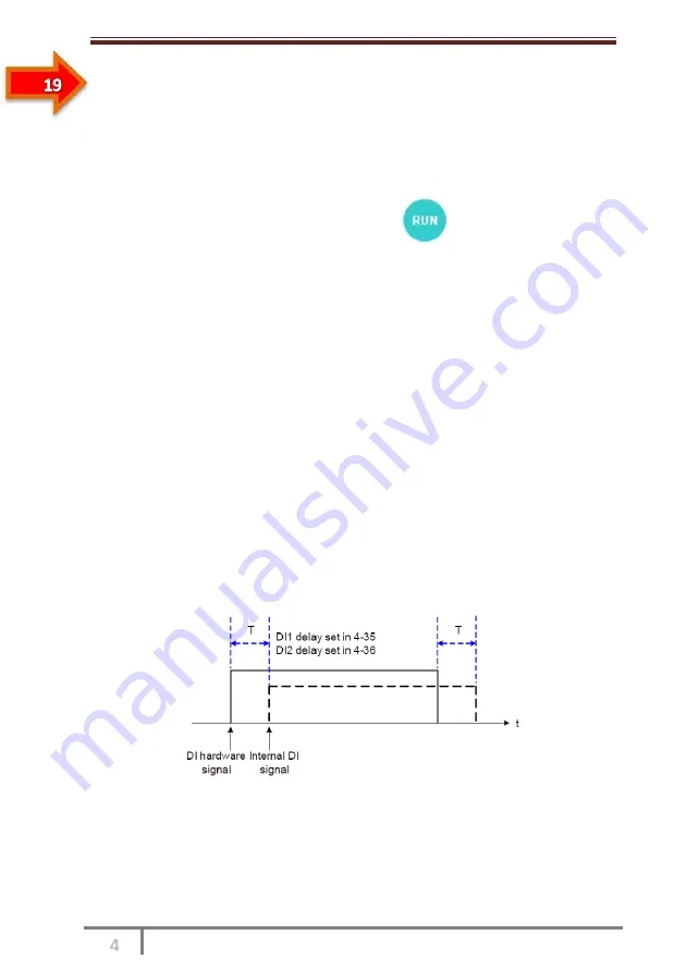
The AC drive also provides P4-10 (DI filter time) for the DI signal to improve the
antiinterference level. For DI1 to DI3, the AC drive provides the DI signal delay function,
convenient for some applications requiring delay.
Figure 4-29 DI delay setting
The preceding 5 DI terminals can be defined in function codes P4-00 to P4-04. Each DI can be
allocated with their respective function from the 50 functions. For details, see descriptions of
P4-00 to P4-04.
The hardware design allows only DI5 to receive high-speed pulse signal. If high-speed
pulse count is required, use DI5.
Содержание SSI700
Страница 1: ......
Страница 3: ...Safety Information and Precautions...
Страница 7: ...Product Information...
Страница 12: ...Mechanical and Electrical Installation...
Страница 19: ...Operation Display and Application Examples...
Страница 42: ...Function Code Table...
Страница 64: ...Description of Function Codes...
Страница 131: ...EMC...
Страница 137: ...Selection and Dimensions...
Страница 141: ...Maintenance and Troubleshooting...