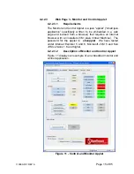
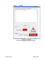
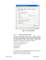
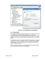

4.2.2.10 Turning the SLM HVOn/Off and Connection Status
Please refer to Figure 11, the Monitor and Control Applet.
Setting Name
Range Values
Local/Remote
Local mode/Remote mode
HV
On/Off
Interlock Open/Closed
Fault Status
OK/Fault
Connection Status Connected/No Data Received/Disconnected
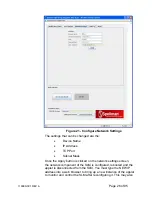
Unlike the controls we previously discussed at the top of the screen
which required a separate dialog screen to enter values, these are
controlled by a button. For example, an On/Off button controls the
HV. When HV is on, the Control is labeled “Click to Turn HV Off”.
When HV is off, the control is labeled “Click to Turn HV On”.
Thereby handling the two distinct states.
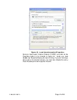
Notice that at the very bottom of the screen is a text field that
displays the current connection status, which as mentioned above
is one of three values. “Connected” is displayed when there exists a
valid TCP/IP session connecting the SLM and the Applet and data
is being received by the applet from the SLM. The next state is “No
Data Received” which is when there is still a valid connection but no
responses have been received from the SLM for 2 seconds. Lastly,
the text field displays “Disconnected” when the TCP/IP session has
been disconnected. To operate the UUT using the Computer
interface the UUT must be set to Remote Mode by Clicking “Click to
Set Remote, the SLM Applet automatically sets the unit to Remote
mode upon connecting
.
When the Applet is first started and anytime the “Click To Connect”
button is clicked there is a 5 second delay as the Applet starts up
the threads necessary for communication between it and the SLM.
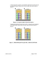
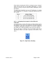
4.2.3 Direct Connection between the SLM and a Computer
A direct Ethernet connection between the SLM and the computer
requires an RJ45 crossover cable. The end connectors will look
identical to a “normal” RJ45 connector but the colors of some of the
wires in the connectors will be “reversed”. Hold up the two ends of
the RJ45 cable and look at the color of the wires from left to right.
They should differ on the two connectors.
118080-001 REV A
Page 20 of 95
Содержание SLM SERIES
Страница 15: ...SLM MANUAL 6 118073 001 Rev C Figure 2 2 Unit Dimensions 1200W ...
Страница 19: ...SLM MANUAL 10 118073 001 Rev C Figure 3 3 Local Programming via External Voltage Source ...
Страница 20: ...SLM MANUAL 11 118073 001 Rev C Figure 3 4 Remote Monitoring ...
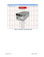
Страница 40: ...Figure 9 Web Page 1 Contact Information 118080 001 REV A Page 13 of 95 ...
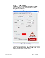
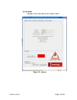
Страница 46: ...4 2 2 9 About Displays version information and model number Figure 15 About 118080 001 REV A Page 19 of 95 ...
Страница 98: ...Request Faults 68 20 ASCII 118080 001 REV A Page 71 of 95 ...


