

SLM MANUAL
8
118073-001 Rev C
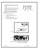
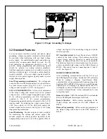
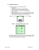
J2 CONTROL I/O
ETHERNET
J4
USB
J5
OUTPUT
LOAD
OUTPUT RETURN
J3
J6
HV OUT
HAZARDOUS VOLTAGE PRESENT
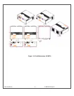
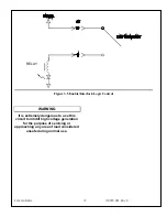
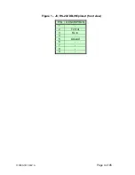
Figure 3.1 Proper Grounding Technique
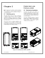
3.2 Standard Features
A note on remote interface circuitry and remote signal
grounding: whenever possible, electrical isolation should
be provided when interfacing with any high voltage
power supply. For enable/disable signal connections, an
isolated relay or optocoupler should be used. For PS
Fault indication an optocoupler should be used. If
possible, analog programming and monitoring signals
should be isolated via analog isolation amplifiers.
Spellman application engineers are available to assist in
interface circuitry design. All interface cables should be
properly shielded. All power supply signals should be
referenced to the power supplies signal ground or power
supply chassis ground
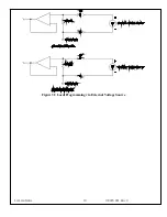
Local Programming potentiometers:
The voltage and
current controls on the front panel can be used as follows:
For local current control, jump J2-2 to J2-7. For local
voltage control, jump J2-3 to J2-5. See Figure 3.2.
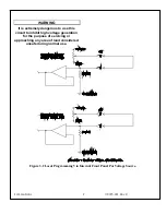
LOCAL PROGRAMMING:
Allows local adjustment
of the output voltage and current level via an external
voltage source. 0-10Vdc signal is supplied to pin 3 of the
J2 for voltage programming and 0-10 Vdc signal is
supplied to Pin 2 J2 for current programming.
Programming signals should be referenced to Pin 9 of J2,
signal ground. By adjusting the voltage source from 0
volts (zero output) to 10 Vdc (full rated output) the
desired output can be selected. See Figure 3.3 for wiring
diagram and specifications.
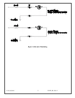
Local Monitoring:
Monitor outputs are made available
for monitoring the voltage and current output. The
monitor outputs are always positive regardless of the
output polarity, where zero 0 to 10 Vdc equals 0-100% of
output. See Figure 3.4 for monitoring wiring and see data
sheet for pin outs.
HV Enable/Interlock:
In Local Mode allows ON/OFF
control of the high voltage. The hardware based dry
contact closure must be closed in to enable the high
voltage. In Remote Mode this I/O acts as an Interlock.
The hardware based dry contact closure must be closed in
order to enable the high voltage via the USB, Ethernet or
RS232. This can be done by connecting pins 11 and 12
on J2. See Figure 3.5.
REMOTE PROGRAMMING:
After establishing communication with the UUT as per
the SLM Digital Protocol spec. Switch the UUT to Remote
Mode by sending a Program Local/Remote Mode
command (this is done automatically upon opening of the
Spellman GUI/APPLET).If the unit is in Local Mode and
enabled prior to switching it to Remote Mode, the UUT
will shutdown and a P.S Fault indictor will occur when it
is switch to Remote Mode. A clear command can be sent
to clear this fault.
Remote Control:
USB, Ethernet and RS232 are standard
Refer to SLM Digital Protocol spec for Details.
Remote Monitor:
Allows remote monitoring of the
Output voltage and current via the USB, Ethernet or
RS232.
Remote Programming:
Allows remote programming of
the Output voltage and current via the USB, Ethernet or
RS232.
Содержание SLM SERIES
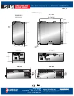
Страница 15: ...SLM MANUAL 6 118073 001 Rev C Figure 2 2 Unit Dimensions 1200W ...
Страница 19: ...SLM MANUAL 10 118073 001 Rev C Figure 3 3 Local Programming via External Voltage Source ...
Страница 20: ...SLM MANUAL 11 118073 001 Rev C Figure 3 4 Remote Monitoring ...
Страница 40: ...Figure 9 Web Page 1 Contact Information 118080 001 REV A Page 13 of 95 ...
Страница 46: ...4 2 2 9 About Displays version information and model number Figure 15 About 118080 001 REV A Page 19 of 95 ...
Страница 98: ...Request Faults 68 20 ASCII 118080 001 REV A Page 71 of 95 ...


